
Connection rod type nozzle mechanism

A connecting rod type and nozzle technology, applied in the field of nozzle mechanism, can solve the problems of complex switch valve structure, influence of product injection molding, short service life, etc., and achieve the effects of low cost, easy maintenance and long service life

Active Publication Date: 2013-03-20
宁波千普机械制造有限公司
View PDF5 Cites 0 Cited by
  • Summary
  • Abstract
  • Description
  • Claims
  • Application Information

AI Technical Summary

Problems solved by technology

[0005] But even if the switch valve is set, since the injection channel and the flow channel in the small barrel are still on the same straight line, when the nozzle leaves the mold, a small amount of plastic melt in the channel between the switch valve and the injection port will still overflow. It will still have a certain impact on the injection molding of the product in the next process, and the structure of the switch valve is relatively complicated, and it is easily damaged after being frequently subjected to the pressure of the plastic melt, and the service life is short

Method used


Image

  • Connection rod type nozzle mechanism
  • Connection rod type nozzle mechanism
  • Connection rod type nozzle mechanism

Examples


Embodiment Construction

[0027] The present invention will be further described in detail below in conjunction with the accompanying drawings and embodiments.

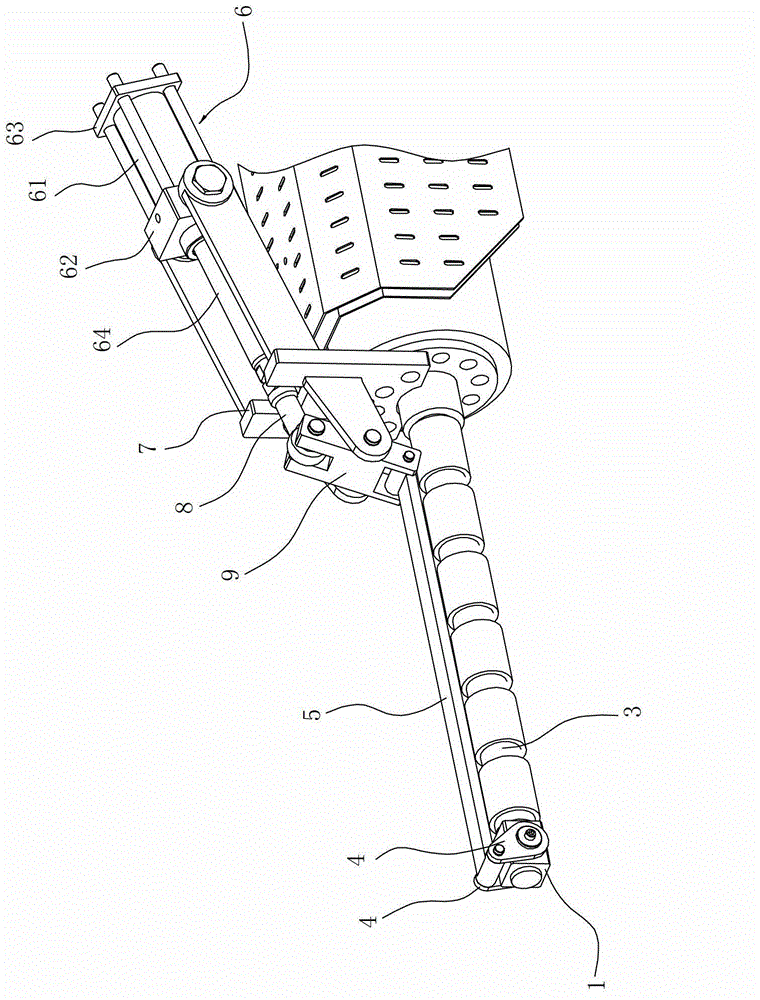
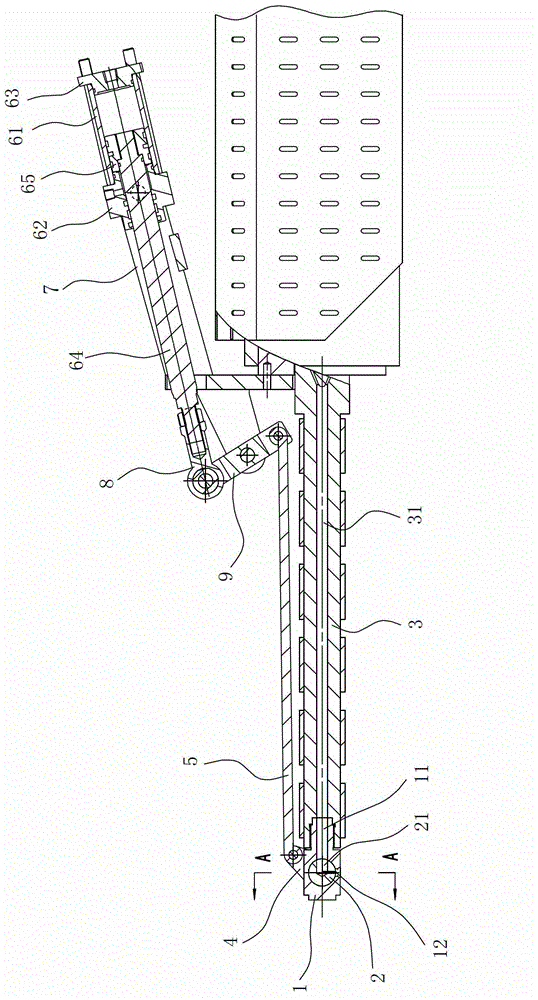
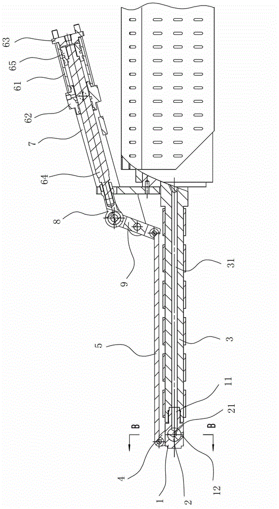
[0028] Such as Figure 1 to Figure 9 As shown, the link type nozzle mechanism includes a nozzle 1, a rotating shaft 2 and a power source, wherein there is an injection channel in the nozzle 1, and the injection channel is composed of a transverse channel 11 connected with an axial flow channel 31 in the small barrel 3 and It is composed of a vertical channel 12 perpendicular to the horizontal channel 11 and with the injection port 121 facing downwards. The nozzle 1 is provided with an axis hole 13 that is located at the junction of the horizontal and vertical channels and is perpendicular to the horizontal and vertical channels. The above-mentioned rotating shaft 2 It is installed in the shaft hole 13 and can rotate relatively. There is a through hole 21 in the rotating shaft 2. In this embodiment, the through hole 21 is designed as an L-shape...


PUM


Abstract

The invention relates to a connection rod type nozzle mechanism, comprising a nozzle provided with a jetting channel therein, wherein the jetting channel consists of transverse and vertical channels which are vertical to each other, a shaft hole located at the jetting channel and vertical to the transverse and vertical channels is formed in the nozzle, a rotating shaft with a through hole is rotationally arranged in the shaft hole, and only under the jetting state, the feed port and the discharge port of the through hole are correspondingly communicated with the jetting hole respectively; the end of the rotating shaft is fixed with one end of a first connection, and the other end of the first connection rod is hinged with one end of a second connection rod which moves under the drive of a power source. In use, the jetting channel can be opened or closed by driving the rotating shaft, thus the jetting port is not required to contact with a die in pre-molding and jetting, and the multi-direction continuous injection and pre-molding composite functions are likely to achieve; meanwhile, the plastic smelt is not liable to remain in the vertical channel due to dead weight, so that the occurrence of overflow phenomenon is effectively avoided when the jetting channel is in the close state; in addition, the connection rod type nozzle mechanism has the advantages of simple overall structure, low cost, convenience in maintaining as well as long service life.

Description

technical field [0001] The invention relates to an injection device, in particular to a nozzle mechanism for injection in the injection device. Background technique [0002] Because the injection device can form products with complex shapes and precise dimensions, and has the advantages of high production efficiency and strong processing adaptability, it is widely used in various fields. During its production, the solid plastic is first plasticized into a plastic product with good plasticity. The plastic melt is injected into the cavity of the molding mold by applying a certain pressure so that the plastic melt has a certain flow rate. After the plastic melt is cooled and shaped in the cavity, the shape consistent with the mold cavity can be obtained. plastic products. [0003] In the above-mentioned injection molding process, the plastic melt enters the mold cavity (formed after the male mold 10' and the female mold 20' are closed) through the nozzle 1'. There is an injec...

Claims


Application Information

Patent Timeline
IPC IPC(8): B29C45/20
Inventor 王金虎洪军翁振涛
Owner 宁波千普机械制造有限公司
Learn More