
Miniature motor and cooling fan having the same

A micro-motor and cooling fan technology, applied to synchronous motors with stationary armatures and rotating magnets, electric components, non-variable pumps, etc., can solve the problem of poor combination stability, easy breakage or damage, and convenient assembly Poor performance and other problems, to achieve the effect of improving the convenience of assembly

Active Publication Date: 2013-03-13
SUNONWEALTH ELECTRIC MACHINE IND
View PDF8 Cites 2 Cited by
  • Summary
  • Abstract
  • Description
  • Claims
  • Application Information

AI Technical Summary

Problems solved by technology

[0005] However, in the process of assembling the printed circuit board 92 and the coil 93 of the existing micro-motor 9 , the coil fixing columns 94 must first be accurately aligned and inserted in the perforations of the printed circuit board 92 and the coil 93 , Only then can the subsequent welding or gluing operations on the tops of the coil fixing columns 94 be carried out. Therefore, the ease of assembly is still not good.
Furthermore, the printed circuit board 92 and the coil 93 are only fixed by the columnar coil fixing column 94, except that the columnar coil fixing column 94 is easily broken or damaged, the printed circuit board 92 and the coil 93 are connected to the coil fixing column 94. The stability of the combination between them is also not good, so it is still necessary to improve

Method used


Image

  • Miniature motor and cooling fan having the same
  • Miniature motor and cooling fan having the same
  • Miniature motor and cooling fan having the same

Examples


Embodiment Construction

[0063] As shown in the figure, in order to make the above and other objects, features and advantages of the present invention more obvious and easy to understand, the preferred embodiments of the present invention are specifically cited below, and in conjunction with the accompanying drawings, the detailed description is as follows:

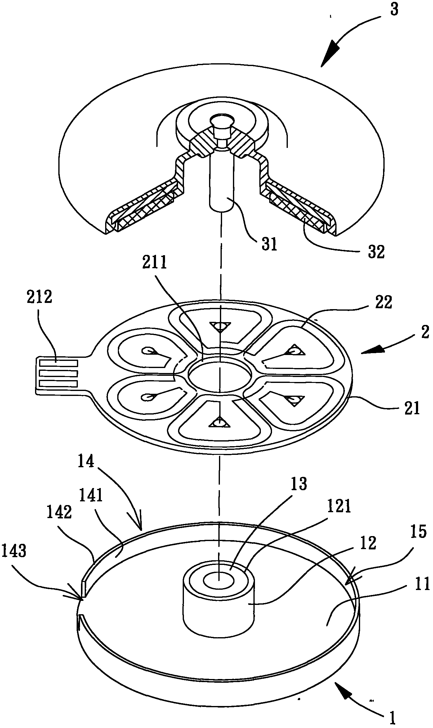
[0064] Please refer to image 3 As shown, the micro motor of the present invention at least includes a base 1 , a stator coil assembly 2 and a rotating member 3 . The base 1 can be combined with the stator coil group 2, and the stator coil group 2 can be connected with an external power supply or drive circuit. 3 rotation actions.

[0065] The base 1 has a coupling surface 11, and the coupling surface 11 is provided with a pivot portion 12, which can be designed in various structures capable of pivotally coupling the rotating member 3; in this embodiment, the pivot The connecting portion 12 is a shaft tube, an opening 121 is formed at an end of...


PUM


Abstract

A miniature motor includes a base having a coupling portion. An engaging portion is provided on a periphery of the base surrounding the coupling portion to form a concave surface therebetween. A stator coil unit includes a substrate mounted on the concave surface. A rotating member is rotatably coupled with the coupling portion and includes a permanent magnet. The base includes a thermoplastic section having a reduced opening. The reduced opening is formed by heating and deforming the thermoplastic section after the stator coil unit is mounted on the concave surface, and the molten and deformed thermoplastic section takes shape to form the reduced opening after cooling. The base can be connected to a frame having an air inlet and an air outlet to form a fan housing, and the rotating member includes blades to form an impeller, providing a cooling fan including the miniature motor.

Description

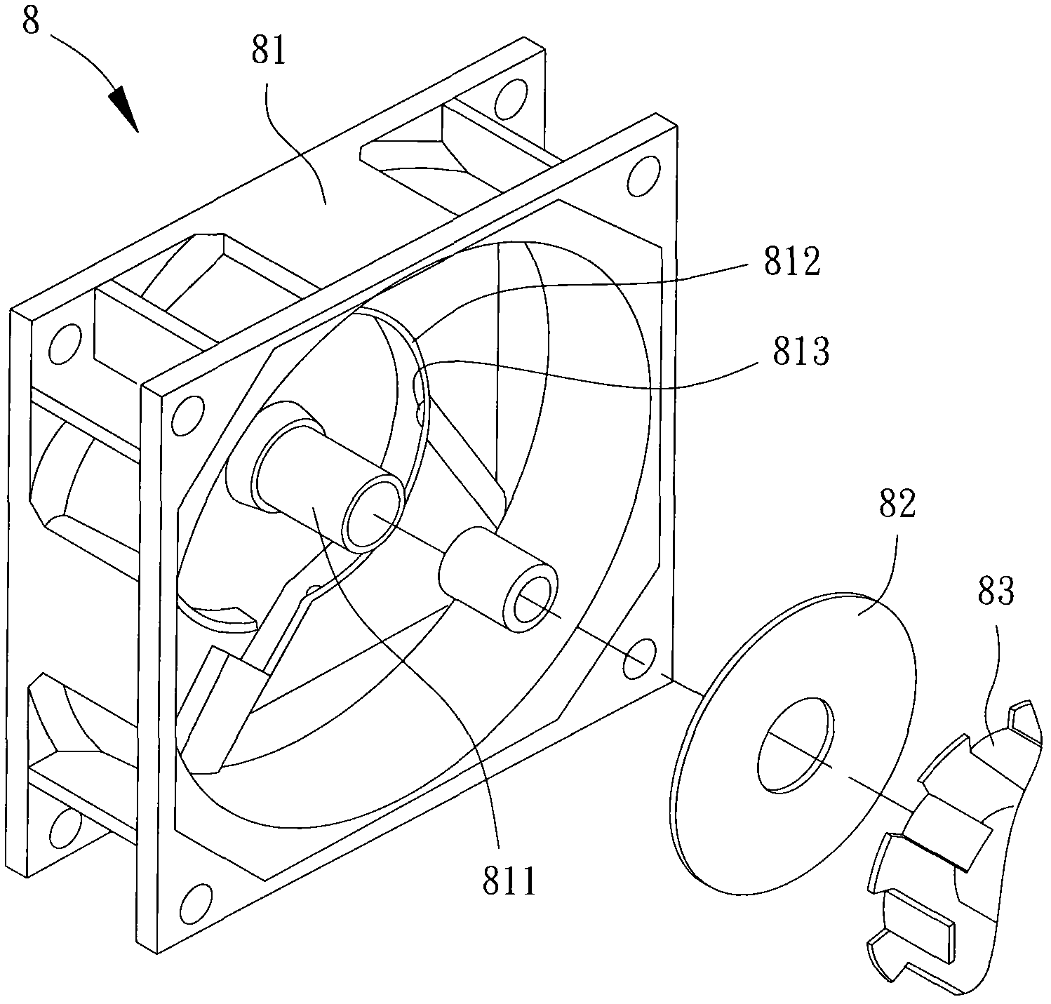
technical field [0001] The present invention relates to a micro motor and a heat dissipation fan with the micro motor, in particular to a micro motor which is easy to assemble and can be stably combined with a stator coil group, and a heat dissipation fan formed by using the micro motor. Background technique [0002] Please refer to the existing technology figure 1 As shown, it is the patent case of Taiwan No. 317321 "A fan structure forming an air gap between an oil-impregnated bearing and a coil", which discloses a more common existing fan 8 at present. The existing fan 8 has a fan base 81. The fan The central position of the base 81 is integrally formed with a cylindrical seat 811, and a protruding ring 812 is formed at the peripheral position of the cylindrical seat 811, and several convex grains 813 are arranged on the inner side of the protruding ring 812; thereby, the protruding ring 812 can For fitting and fixing components such as the circuit board 82 and the stato...

Claims


Application Information

Patent Timeline
Patent Type & Authority Applications(China)
IPC IPC(8): H02K21/22H02K15/06F04D25/08
CPCF04D25/0653H02K21/24H02K2203/03H02K3/47
Inventor 单多年郑元杰
Owner SUNONWEALTH ELECTRIC MACHINE IND
Learn More