Swing unit for placating infants

A rocking device and baby technology, which is applied in the field of rocking devices for comforting babies, can solve the problems of high production cost, small application range, and human injury, and achieve the effects of low production cost, low power consumption, and cost saving

Active Publication Date: 2013-03-13
嘉善创越知识产权服务有限公司
View PDF5 Cites 7 Cited by
  • Summary
  • Abstract
  • Description
  • Claims
  • Application Information

AI Technical Summary

Problems solved by technology

Although its design is ingenious, its power is driven by electromagnetic force. It has been scientifically proven that the electromagnetic field will
[0003] The human body causes a certain degree of damage, especially the impact on the brain, so the baby will be more affected by the electromagnetic field. In addition, the swing structure is realized by swinging, not only the structure is more complicated, but also the production cost High, and the biggest disadvantage is that the swing device must be matched with the crib before it can be used, that is, the swing device can only be installed at the set position, so the scope of application is small, so its structure needs to be further improved

Method used


Image

  • Swing unit for placating infants
  • Swing unit for placating infants
  • Swing unit for placating infants

Examples


Embodiment 1

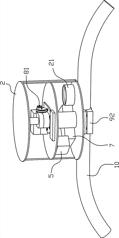
[0032] Embodiment one, such as Figure 1 to Figure 12 As shown, the rocking device of this embodiment includes a motor 1 and a housing 2 that can be fixed with the infant soothing device. The motor 1 is fixed on the partition 12 in the housing 2. The inner peripheral walls of the body 2 are fixed together. The output shaft 11 of the motor 1 is linked by a transmission device that can make the counterweight 51 rotate horizontally to generate centrifugal force and drive the vibration of the infant soothing device; the transmission device includes a rotating shaft 4 and a centrifugal block 5, and the centrifugal force One end of the block 5 is connected with the counterweight 51: the centrifugal block 5 is a sector block in the shape of a fan, the center end of the sector block is fixed to the rotating shaft 4, and the arc end of the sector block is provided with a top The arc-shaped concave cavity 52 of the opening, the counterweight 51 is inserted in the arc-shaped concave cav...

Embodiment 2

[0033] Embodiment two, such as Figure 13As shown, the rocking device of this embodiment is similar to the structure of the above rocking device, except that the structure of the device and the fixed rod 10 is detachable and fixed: the top of the housing 2 is provided with a concave cavity on the top surface A fixed plate 93 is provided above the fixed plate 93, and a paired plate 94 is provided. The bottom surface of the paired plate 94 is provided with a recessed portion. When the housing 2 and the fixed rod 10 are together, the fixed rod 10 is embedded in the recess. part and the recessed cavity, and the plywood 94 is fixed together with the fixing plate 93 by screws 95 or bolts.

Embodiment 3

[0034] Embodiment 3 is another structural embodiment of the present invention, its basic structure is the same as above, the difference is the centrifugal structure, see Figure 14 and Figure 15 As shown, the transmission device includes a rotating shaft 4 and a centrifugal block 5, and one end of the centrifugal block 5 is fixed to the rotating shaft 4 capable of horizontal rotation, and the other end of the centrifugal block 5 is connected to the rotating shaft 5 through a stay cord 50. The hanging ball 53 of the counterweight is connected, and the hanging ball 53 can make a horizontal circular motion around the inner cavity of the housing 2 under the drive of the rotating shaft 4 , which is linked with the output shaft 11 of the motor 1 .


PUM


Abstract

The invention discloses a swing unit for placating infants. The swing unit comprises a motor (1) and a casing (2) which can be fixed with an infant placating device, and the motor (1) is arranged in the casing (2). The swing unit is characterized in that an output shaft (11) of the motor is linked with a transmission which enables a counter weight block (51) to rotate horizontally to produce the centrifugal force to drive the infant placating device to swing. The swing unit for placating infants has the advantages that the horizontal rotating counter weight block rotates centrifugally in the casing, not only the design is ingenious, the size is small, the manufacture cost is low, the swing is stable, the swing unit can be mounted on different infant placating devices, only a swing unit can be used for multiple purposes, costs of users can be saved, and the application range is wide; and the structure of the unit is simple, power is saved, and the transmission unit uses a transmission belt and a worm and gear for transmission so that the operation is stable and the noise is low.

Description

technical field [0001] The invention relates to the technical field of making baby products, in particular to a rocking device for soothing babies. Background technique [0002] An existing Chinese utility model patent No. CN200420094809.7 titled "A Swing Crib" discloses a piece of furniture, which includes an outer bracket and an inner bracket, the top ends of both sides of the inner bracket are connected to the The outer brackets are pivotally connected; and a driving device is arranged between the outer bracket and the inner bracket, and the driving device includes a circuit-controlled electromagnet and a permanent magnet, which are respectively arranged on the outer bracket or the inner bracket. on the inner bracket. The product of the present invention adopts the pivot joint structure of the outer bracket and the inner bracket, and drives between the inner and outer brackets. Although its design is ingenious, its power is driven by electromagnetic force. It has been s...

Claims


Application Information

Patent Timeline
Patent Type & Authority Applications(China)
IPC IPC(8): H02K7/075H02K7/10A47D9/02B62B9/22
Inventor 吴冬俊姚春超
Owner 嘉善创越知识产权服务有限公司
Why Eureka
Try Eureka