Pre-charging circuit

A pre-charging circuit and resistor technology, applied in the direction of circuit devices, emergency protection circuit devices, emergency protection circuit devices for limiting overcurrent/overvoltage, etc., can solve complex structure, high cost, redundant pre-charging circuit structure and other problems, to achieve the effect of reducing manufacturing cost, simple structure, simple and effective structure

Active Publication Date: 2013-03-13
陕西天天出行科技有限公司
View PDF7 Cites 5 Cited by
  • Summary
  • Abstract
  • Description
  • Claims
  • Application Information

AI Technical Summary

Problems solved by technology

The traditional pre-charging circuit is to set the pre-charging resistor and switching circuit to protect the soft start, or to perform pre-charging protection through the integrated pre-charging chip module. The former requires a two-part stru

Method used


Image

  • Pre-charging circuit

Examples


Embodiment Construction

[0033] The specific implementation manner of the present invention will be described below in conjunction with accompanying drawing, and the embodiment of the present invention will be described in further detail below in conjunction with accompanying drawing, and the following description about the embodiment of the present invention is only exemplary, not in order to limit the subject matter to be protected of the present invention For the embodiments described in the present invention, there are other changes within the protection scope of the claims, which all belong to the subject matter required to be protected in the present invention.

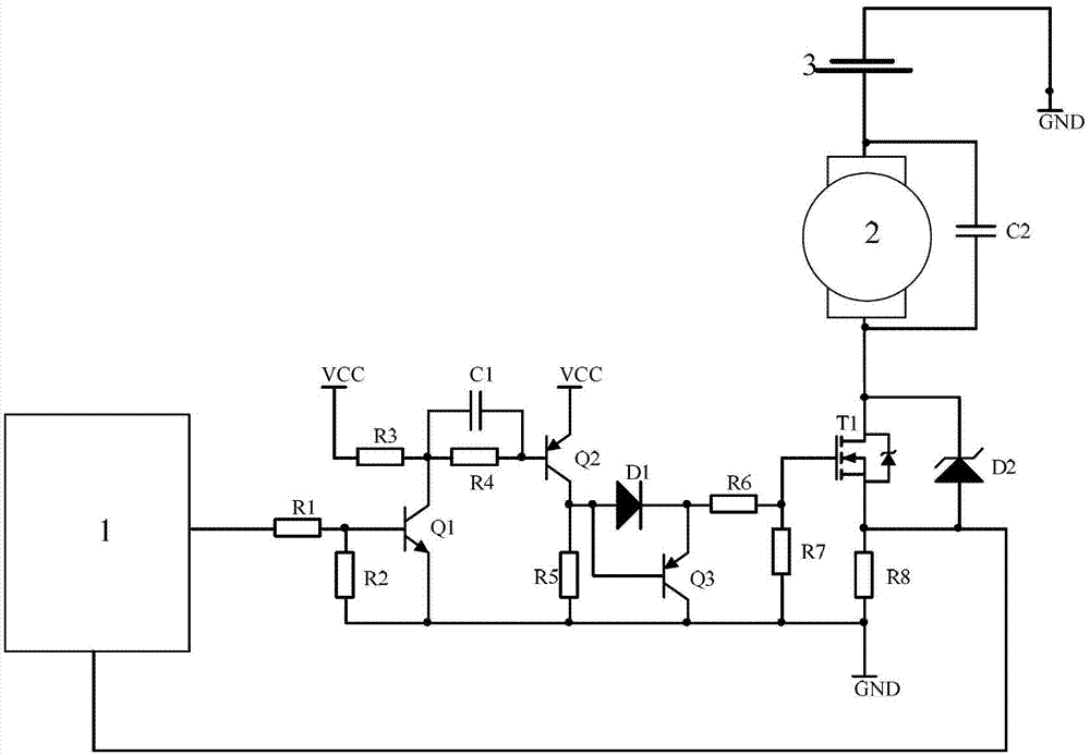
[0034] As shown in Figure 1, in the pre-charging circuit, the single-chip microcomputer 1 is connected to one end of R1; one end of R1 is connected to the single-chip microcomputer 1, and the other end is connected to the base of the transistor Q1; one end of the resistor R2 is connected to the base of the transistor Q1, and the other end...


PUM


Abstract

The invention discloses a pre-charging circuit. One end of a resistor R1 is connected with a single chip microcomputer (1), and the other end of the resistor R1 is connected with a base electrode of an audion Q1. One end of a resistor 2 is connected with a base electrode of the audion Q1, and the other end is grounded. One end of a resistor R3 is connected with a collector electrode of the audion Q1, and the other end of the resistor R3 is connected with a voltage to current converter (VCC). An emitting electrode of the audion Q1 is grounded. One end of a resistor R4 is connected with the collector electrode of the audion Q1, and the other end of the resistor R4 is connected with a base electrode of an audion Q2. One end of a capacitor C1 is connected with the collector electrode of the audion Q1, and the other end of the capacitor C1 is connected with the base electrode of an audion Q2. One end of a resistor R5 is connected with a collector electrode of the audion Q2, and the other end of the resistor R5 is grounded. One end of a resistor R6 is connected with an emitting electrode of the audion Q3, and the other end of the resistor R6 is connected with a grid electrode of a transistor T1. One end of a resistor 7 is connected with the grid electrode of the transistor T1, and the other end of the resistor 7 is grounded. One end of a resistor R8 is grounded, and the other end of the transistor T1 is connected with a source electrode of the transistor T1. The pre-charging circuit aims at overcoming the shortcomings in the prior art and is simple and reliable in structure and low in cost.

Description

technical field [0001] The invention belongs to the field of protective circuit devices that limit overcurrent or overvoltage without cutting off the circuit, and in particular relate to a precharging circuit that uses the switching function of a MOSFET transistor to realize soft start. Background technique: [0002] In order to realize the load regulation effect on electricity consumption, a voltage stabilization capacitor is usually connected to both ends of the load, but when the circuit starts to supply power, at the moment the switch is closed, the capacitor will generate a large current, which impacts the voltage stabilization capacitor, making the voltage stabilization capacitor Equivalent to a circuit breaker. Therefore, in this case, a soft start of the circuit is required, that is, a pre-charge circuit is set. The traditional pre-charging circuit is to set the pre-charging resistor and switching circuit to protect the soft start, or to perform pre-charging protect...

Claims


Application Information

Patent Timeline
IPC IPC(8): H02H9/02H02H9/04
Inventor 贾海江何斌
Owner 陕西天天出行科技有限公司
Why Eureka
Try Eureka