
Method for multi-focal-plane object imaging under microscopic vision

A technology of microscopic vision and multi-focal planes, which is applied in image enhancement, image analysis, image data processing, etc., can solve problems such as no method for obtaining depth information, achieve remarkable results, improve computing speed, and image clarity high effect

Inactive Publication Date: 2013-03-13
INST OF AUTOMATION CHINESE ACAD OF SCI
View PDF2 Cites 27 Cited by
  • Summary
  • Abstract
  • Description
  • Claims
  • Application Information

AI Technical Summary

Problems solved by technology

This method has a good effect on multi-focal plane image fusion, but it does not give a method for obtaining the depth information of objects in three-dimensional space.

Method used


Image

  • Method for multi-focal-plane object imaging under microscopic vision
  • Method for multi-focal-plane object imaging under microscopic vision
  • Method for multi-focal-plane object imaging under microscopic vision

Examples


Embodiment Construction

[0020] In order to make the object, technical solution and advantages of the present invention clearer, the present invention will be described in further detail below in conjunction with specific embodiments and with reference to the accompanying drawings.

[0021] It should be noted that, in the drawings or descriptions of the specification, similar or identical parts all use the same figure numbers. Implementations not shown or described in the accompanying drawings are forms known to those of ordinary skill in the art. Additionally, while illustrations of parameters including particular values ​​may be provided herein, it should be understood that the parameters need not be exactly equal to the corresponding values, but rather may approximate the corresponding values ​​within acceptable error margins or design constraints. In addition, the directional terms mentioned in the following embodiments, such as "upper", "lower", "front", "rear", "left", "right", etc., are only re...


PUM


Abstract

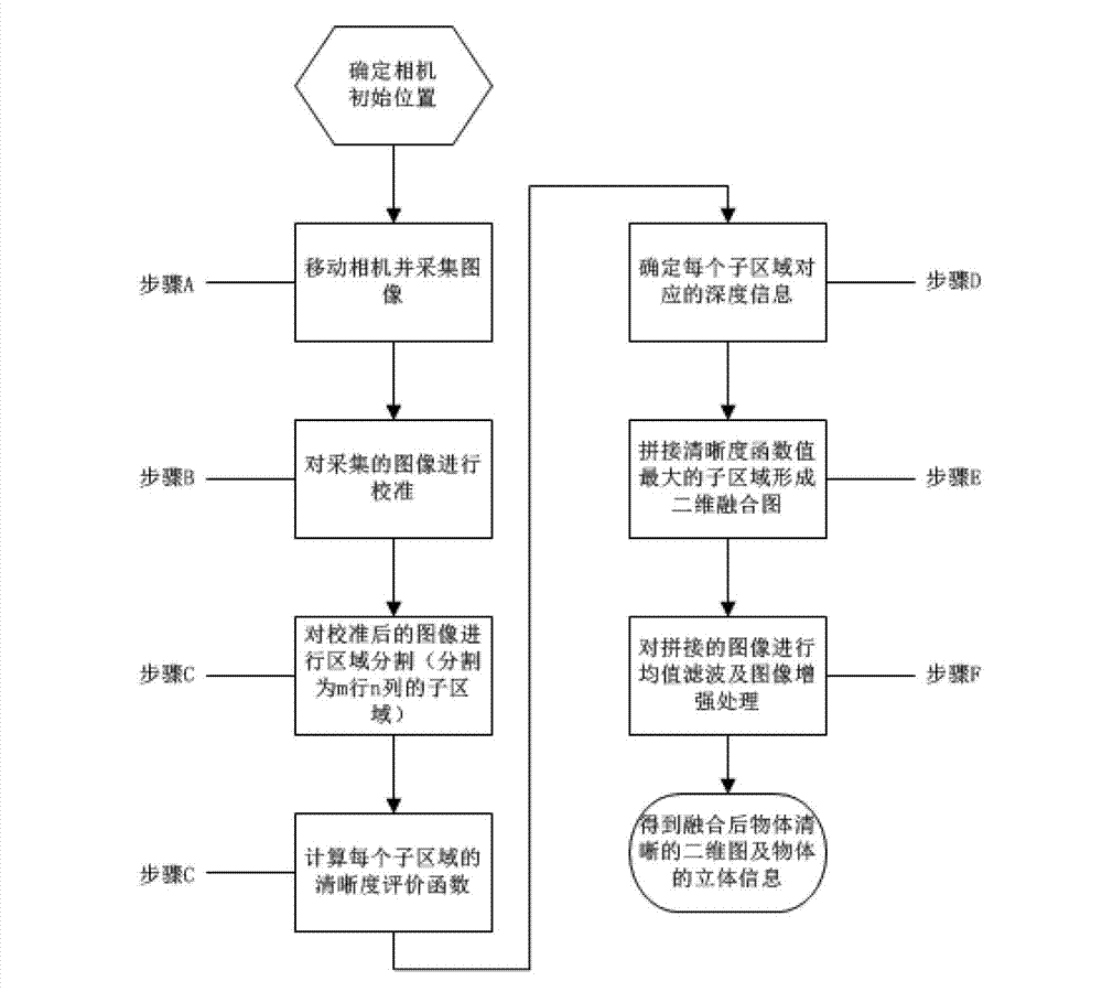
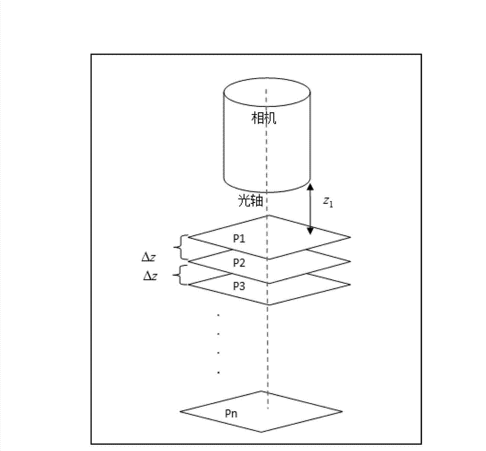
The invention provides a method for multi-focal-plane object imaging under microscopic vision. The method comprises moving a camera along the direction of a primary optical axis, collecting a plurality of images of a multi-focal-plane object, forming an image sequence, and enabling the plurality of images to record the process of vagueness to clearness and then to vagueness of imaging of the multi-focal-plane object; correcting images in the image sequence, and enabling regions of the surface in which the multi-focal-plane object is located according to the images to be the same; dividing each image in the image sequence into sub-regions with m lines and n columns, performing definition evaluation on each sub-region image, and obtaining definition evaluation function values of each sub-region image; finding out a corresponding image serial number when the definition evaluation function value is the maximum for each sub-region, obtaining the position of the camera relative to the object at the time, and obtaining depth information of the sub-region in a three-dimensional space through position information of the camera relative to the object. According to the method, the depth information of the object in the regions can be positioned rapidly.

Description

technical field [0001] The invention relates to the fields of computer vision and image processing, in particular to a method for imaging multi-focal plane objects under microscopic vision. Background technique [0002] When visually detecting tiny objects, since the depth of the tiny objects is much greater than the depth of field of the microscopic camera, a clear image of the entire object cannot be obtained through one focusing of the microscopic camera. Most of the existing multi-focal plane image fusion methods use wavelet transform. This method has a good effect on multi-focal plane image fusion, but it does not provide a method for obtaining the depth information of objects in three-dimensional space. Contents of the invention [0003] (1) Technical problems to be solved [0004] In order to solve one or more of the above problems, the present invention provides a method for imaging a multi-focal plane object under microscopic vision, so as to obtain the depth in...

Claims


Application Information

Patent Timeline
Patent Type & Authority Applications(China)
IPC IPC(8): G06T7/00G06T5/50
Inventor 王欣刚徐德张正涛尹英杰白明然
Owner INST OF AUTOMATION CHINESE ACAD OF SCI
Learn More