
Calculation method of sound field distribution of phased array ultrasonic probe in flaw detection in multilayer medium

A technology of ultrasonic probe and multi-layer medium, applied in the direction of processing the response signal of detection, to achieve the effect of assisting process design, defect evaluation, and fast calculation

Active Publication Date: 2013-03-13
ELECTRIC POWER RES INST OF GUANGDONG POWER GRID +1
View PDF6 Cites 23 Cited by
  • Summary
  • Abstract
  • Description
  • Claims
  • Application Information

AI Technical Summary

Problems solved by technology

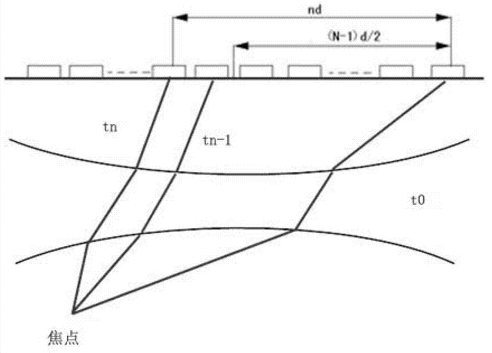
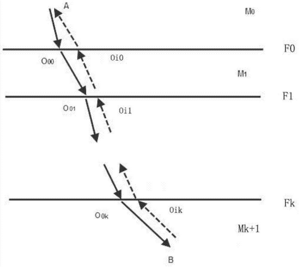
[0005] The technical problem to be solved by the present invention is to propose a calculation method for the sound field distribution when the phased array ultrasonic probe detects flaws in a multi-layer medium, to carry out the process design and defect echo analysis of the multi-layer complex structure phased array ultrasonic detection, and It provides the possibility to implant the wafer delay rule algorithm for multi-layer structure detection on the phased array ultrasonic testing instrument, so as to improve the detection efficiency under the premise of ensuring the detection ability

Method used


Image

  • Calculation method of sound field distribution of phased array ultrasonic probe in flaw detection in multilayer medium
  • Calculation method of sound field distribution of phased array ultrasonic probe in flaw detection in multilayer medium
  • Calculation method of sound field distribution of phased array ultrasonic probe in flaw detection in multilayer medium

Examples


Embodiment example

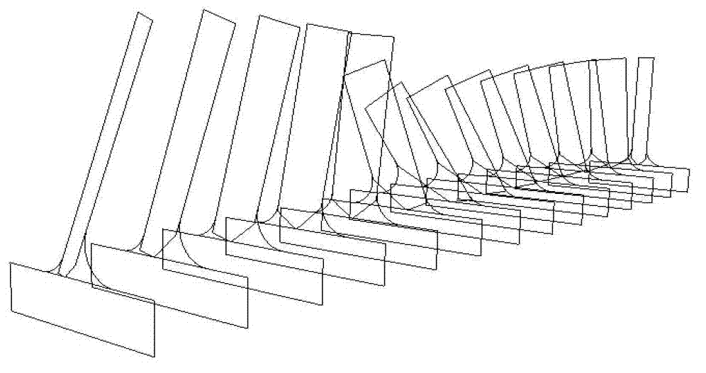
[0038] Implementation case: The welding seam connecting the turbine runner blade with the upper crown and lower ring is prone to fatigue cracks due to alternating stress during service. The thickness of the weld seam of the runner changes continuously from the water inlet side to the water outlet side. The phased array detection process design usually divides the weld seam into a series of detection areas with small thickness differences, and independently designs the parameters of each area, such as image 3 shown. The acoustic beam propagation medium composed of phased array probe wedges and runner welds can also be regarded as a multi-layer medium with large acoustic differences.

[0039]This algorithm is used to calculate the sound field distribution of the phased array probe in the wheel structure. The parameters of the phased array probe are frequency 2.25MHz, the size of a single chip is 0.5*10mm, and the gap between chips is 0.1mm. When the point source is discrete, ea...


PUM

PropertyMeasurementUnit
thicknessaaaaaaaaaa

Abstract

A calculation method of sound field distribution of a phased array ultrasonic probe in flaw detection in a multilayer medium. The method comprises the steps of: S1, modifying a Rayleigh integral expression to obtain an expression of phased array sound field transmission; S2, establishing a fast algorithm of path in an arbitrary multilayer medium; and S3, calculating chip delay time and excitation delay time: S3-1, establishing a three-dimensional system of coordinates comprising a probe wafer, a wedge and a work piece; S3-2, conducting Fourier transform on a drive signal; S3-3, forming a path matrix; S3-4, calculating a point source delay time, diffusion attenuation, and reflection and transmission through each section; S3-5, calculating sound field amplitude and phase transformation generated from a target signal, and conducting inverse transformation to obtain sound field from each point source drive signal transmitting to the target calculation point; S3-6, superimposing to obtain sound field value at the target point; and S3-7, dividing units and sequentially calculating to obtain sound field distribution in the target area. The invention can effectively assist process design and defect evaluation phased array detection of complex multilayer structure.

Description

technical field [0001] The invention relates to a calculation method for ultrasonic sound field distribution, in particular to a calculation method for sound field distribution when a phased array ultrasonic probe detects flaws in multi-layer media. Background technique [0002] The phased array ultrasonic probe is composed of a group of relatively independent chips, and each independent chip can emit ultrasonic beams. All or part of the chips are excited according to different rules, so that the ultrasonic beams emitted by the chips at different excitation times are superimposed to form different wave fronts, so that the effects of beam deflection, focusing and scanning can be controlled. Compared with conventional ultrasonic testing, the advantages of phased array flaw testing are: (1) When the probe does not move or moves in a small range, a large sound beam coverage can be obtained, which can be used to solve the problem of complex spatial structures that limit the detec...

Claims


Application Information

Patent Timeline
Patent Type & Authority Applications(China)
IPC IPC(8): G01N29/44
Inventor 肖凯张俊胡平李晓红马庆增张益成
Owner ELECTRIC POWER RES INST OF GUANGDONG POWER GRID
Learn More