Valve arrangement

A technology of valve device and valve hole, which is applied in the direction of valve device, valve operation/release device, fluid pressure actuation device, etc., to achieve the effect of reducing manufacturing cost, saving space and requiring less space

Active Publication Date: 2014-11-19
ROBERT BOSCH GMBH
View PDF8 Cites 0 Cited by
  • Summary
  • Abstract
  • Description
  • Claims
  • Application Information

AI Technical Summary

Problems solved by technology

[0005] The disadvantage of this valve is that only one valve is accommodated in the sleeve

Method used


Image

  • Valve arrangement
  • Valve arrangement
  • Valve arrangement

Examples


Embodiment Construction

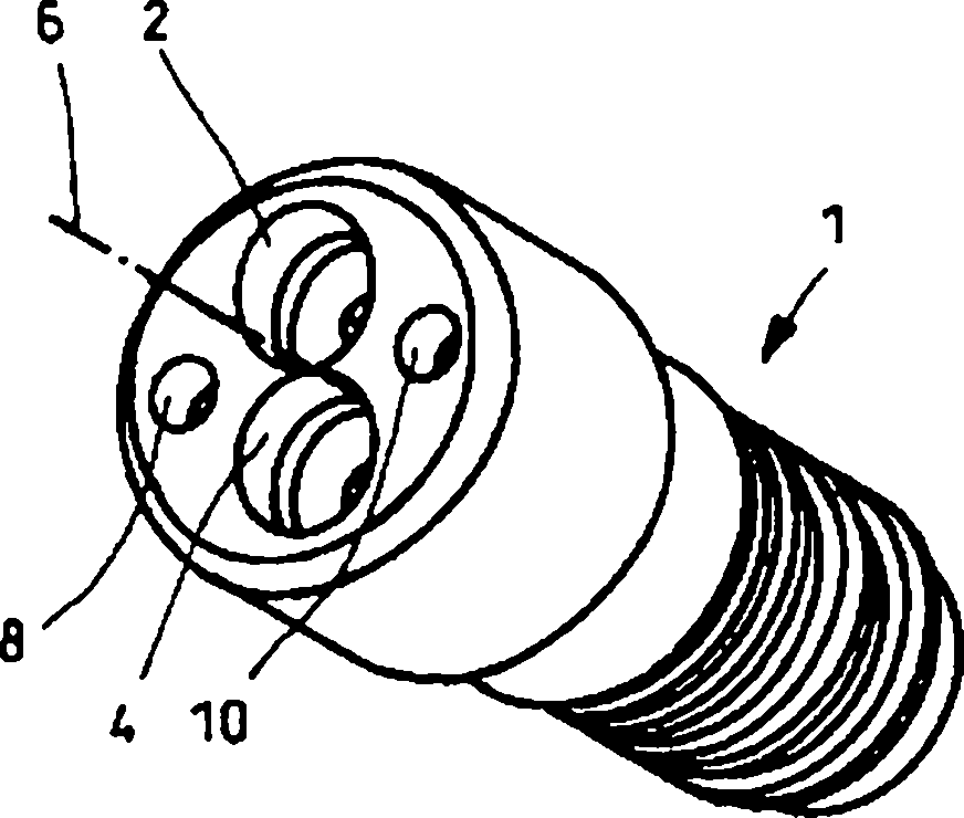
[0038] figure 1 A first exemplary embodiment of the valve device according to the invention is shown in a perspective view. The housing of the valve device is designed as a mounting sleeve 1 which can be screwed into an adjustable pump (not shown in detail). In this case, the mounting sleeve 1 rotates about its center axis 6 . Different interfaces are set on the outer circumference of the installation sleeve 1, and these interfaces refer to image 3 to explain. These connections are in a pressure medium connection with two different valves which are jointly arranged in the mounting sleeve 1 .

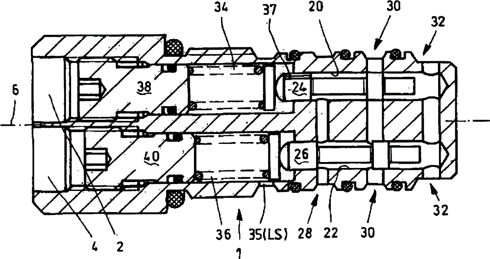
[0039] Each valve has as image 3 Valve holes 20, 22 are shown, and where figure 1 Only the end section arranged on the end side can be seen here. Corresponding openings 2 , 4 are therefore arranged on the end faces, which are arranged at a distance from the center axis 6 of the mounting sleeve 1 and are arranged diametrically opposite one another.

[0040] In addition, diametric...


PUM


Abstract

A valve arrangement includes at least two valves and a housing which is configured as an installation cartridge. One of the valves is configured as a pressure regulator and the other of the valves is configured as a delivery flow regulator. The valve arrangement is configured to be inserted or screwed into a variable-displacement pump, thereby minimizing the spatial requirement of the valve arrangement.

Description

technical field [0001] The invention relates to a valve arrangement according to the preamble of claim 1 . Background technique [0002] A housing in the form of a sleeve is known in a valve arrangement according to the prior art, which can be inserted into an opening of a hydraulic system. [0003] Document DE 10 2007 044 451 A1 shows such a pressure regulating valve which has a housing in the form of a sleeve which is screwed into a connecting plate of a hydrostatic piston compressor. [0004] Document GB 2 367 095 A likewise shows a pressure regulating valve, and document DE 296 20 927 U1 shows a non-return valve in the form of a sleeve. [0005] A disadvantage of this valve is that only one valve is accommodated in the sleeve. [0006] Furthermore, it is known from the prior art to combine two valves in a housing. Document DE 101 36 416 A1 shows such a combination of a pressure regulating valve and a delivery flow regulating valve. The housings of the two valves are ...

Claims


Application Information

Patent Timeline
Patent Type & Authority Patents(China)
IPC IPC(8): F16K27/00F15B13/08
CPCF16K27/041F15B2211/20553F15B11/165F16K43/00F16K31/1225F16K11/07F16K31/363F15B13/0835Y10T137/598Y10T137/7668Y10T137/2557Y10T137/7559Y10T137/87893F16K27/02F16K31/122
Inventor C·施皮尔福格尔
Owner ROBERT BOSCH GMBH
Why Eureka
Try Eureka