
Aircraft fuselage made out with composite material and manufacturing processes

A manufacturing method and aircraft technology, which are applied in the field of aircraft fuselage and can solve problems such as difficulty in realizing the integration of truss beam heights and the like

Inactive Publication Date: 2013-03-06
AIRBUS OPERATIONS SL
View PDF9 Cites 8 Cited by
  • Summary
  • Abstract
  • Description
  • Claims
  • Application Information

AI Technical Summary

Problems solved by technology

[0007] Among other things, this fuselage structure has the problem that, in the case of a fuselage made of composite materials, the large number of girders makes a high degree of integration difficult to achieve

Method used


Image

  • Aircraft fuselage made out with composite material and manufacturing processes
  • Aircraft fuselage made out with composite material and manufacturing processes
  • Aircraft fuselage made out with composite material and manufacturing processes

Examples


Embodiment Construction

[0024] Circumferential orientation of fuselage panels

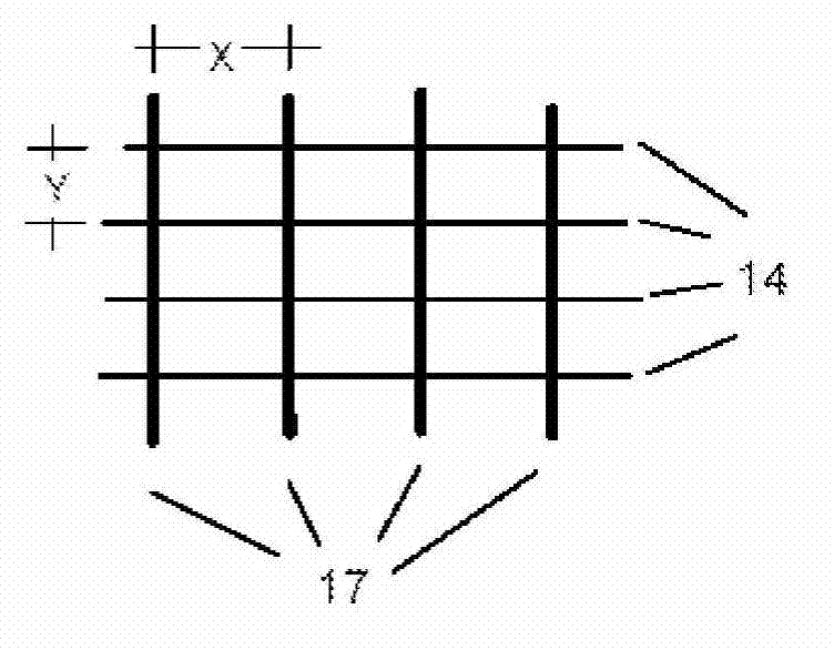
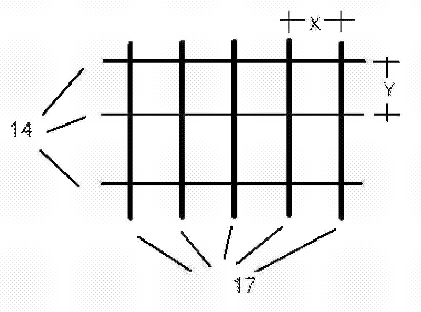
[0025] In contrast to the longitudinal orientation of the panels in known fuselages, the basic idea of ​​the invention is to construct the fuselage section of the aircraft in such a way that its panels are oriented circumferentially. Among known airframes, such as Figure 1a As shown, the distance X between the frames 17 is greater than the distance Y between the girders 14, and in the fuselage section according to the present invention, as Figure 1b As shown, the distance X between the frames 17 is less than the distance Y between the girders 14 .

[0026] In known fuselages, a typical value for the X / Y ratio may be 2.5, whereas for the fuselage according to the invention it may be 0.6.

[0027] A first effect of the circumferential orientation of the plates is that the plates take advantage of the curvature of the fuselage to resist longitudinal loads, thereby delaying the onset of buckling. The increased postbucklin...


PUM


Abstract

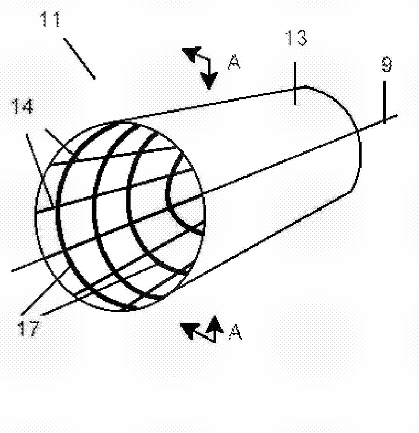
Aircraft fuselage made out with composite material and manufacturing processes. The structure of the fuselage (1 1 ) comprises a skin (13), a plurality of frames (17) positioned transversely to the longitudinal axis (9) of the fuselage (11) and a plurality of longitudinal stiffening elements (14, 15) that can be either stringers (14) or beams (15), being the ratio between the distance (X) between frames (17) and the distance (Y) between longitudinal stiffening elements (14, 15) is less than one. If the stiffening elements are stringers (14) the manufacturing process is based on assembling the fuselage section (11) joining the skin (13) with the stringers (14) to the frames (17). If the stiffening elements are beams (15) the manufacturing process is based on joining the skin to an internal structure made up with frames (17) and beams (15).

Description

technical field [0001] The present invention relates to an aircraft fuselage, and more particularly, relates to an aircraft fuselage completely made of composite materials, and also relates to a manufacturing method of the aircraft fuselage. Background technique [0002] It is generally known that the aerospace industry requires structures to support the loads they are subjected to while meeting high stiffness and resistance requirements on the one hand and to be as light as possible on the other hand. This requirement has led to a continued expansion of the use of composite materials in primary structures, since the substantial weight savings that can be achieved through the easy application of these materials compared to structures designed in metallic materials. [0003] Integrated structures have proven to be particularly effective in this regard. When all structural parts of a structure are manufactured in one go, the structure is called a unitary structure. This is a...

Claims


Application Information

Patent Timeline
Patent Type & Authority Applications(China)
IPC IPC(8): B64C1/06
CPCB64C2001/0072Y02T50/43Y02T50/433B64C1/064B64C1/068B64C1/061Y10T29/49826Y10T156/1002Y10T29/49957Y02T50/40
Inventor 埃莱娜·阿莱瓦洛·罗德里格斯弗朗西斯科·乔斯·克鲁斯·多明戈斯
Owner AIRBUS OPERATIONS SL
Learn More