LED support

A technology of LED bracket and bracket body, applied in the field of LED bracket, can solve the problems of unstable use, no electroplating layer, inability to maintain electrical continuity between the test head and the pin end, etc.

Inactive Publication Date: 2013-03-06
苏州爱来特光电科技有限公司
View PDF4 Cites 0 Cited by
  • Summary
  • Abstract
  • Description
  • Claims
  • Application Information

AI Technical Summary

Problems solved by technology

[0004] The LED seat monomer formed by the above-mentioned LED bracket, after the pins are punched, the punched section does not have a pre-plated electroplating layer, which is prone to oxidat

Method used


Image

  • LED support
  • LED support
  • LED support

Examples


Embodiment Construction

[0017] The following will clearly and completely describe the technical solutions in the embodiments of the present invention with reference to the drawings in the embodiments of the present invention.

[0018] The invention provides an LED bracket to achieve the purposes of improving product quality and saving costs.

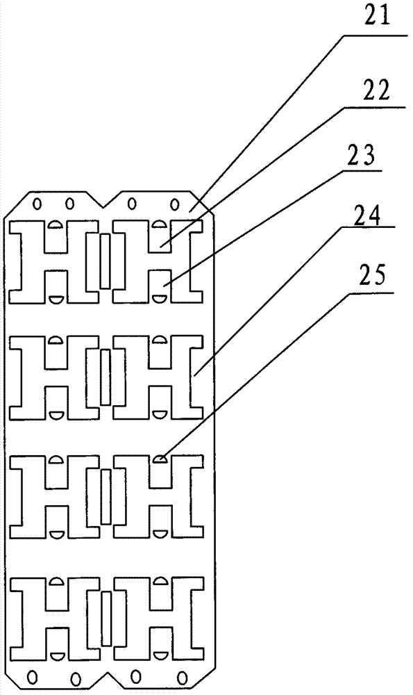
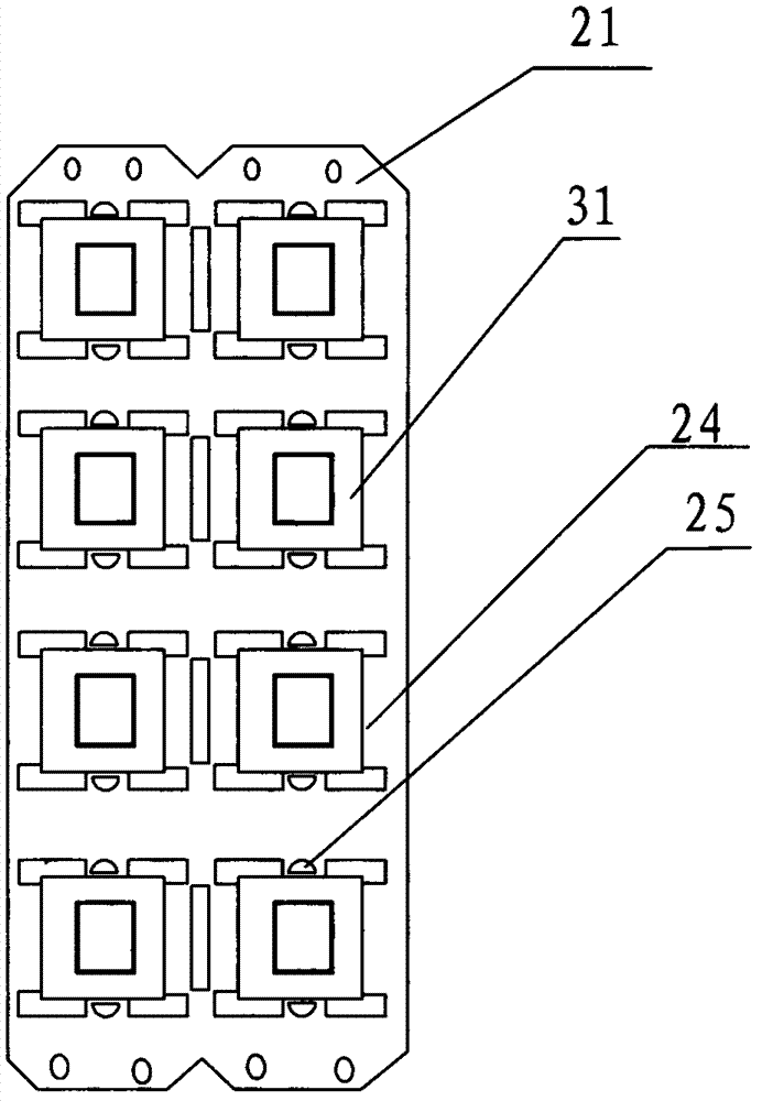
[0019] Such as figure 2 , image 3 As shown, the LED bracket disclosed in the present invention includes a bracket body 21, a plurality of support frames are arranged on the bracket body 21, and pin one 22 and pin two 23 are arranged on each support frame, and the plastic seat 31 is formed on the pin 1 and pin 2, so that one end of pin 1 and pin 2 is exposed inside the plastic seat 31, and the other end passes through the plastic seat to connect with the supporting frame. The pins are combined with the plastic seat to form an LED seat body, and a pair of support pieces 24 are arranged on both sides of the support frame to support the LED seat body.

[0020]...


PUM


Abstract

The invention discloses an LED support which comprises a support body. A plurality of supporting frames are arranged on the support body, pins in specified quantity are arranged on the supporting frames, plastic seats are arranged on the pins by means of plastic injection, one end of each pin is exposed in the corresponding plastic seat while the other end of each pin penetrates through the corresponding plastic seat to be connected with the corresponding supporting frame, and the other end, connected with the corresponding supporting frame, of each pin is provided with a punched hole. Using the LED support can guarantee product quality and save cost.

Description

technical field [0001] The invention relates to the technical field of LEDs, in particular to an LED bracket. Background technique [0002] LEDs are widely used. They can be used not only for lighting, but also for some electronic products, such as backlights on TV sets. For LEDs in different application fields, different LED brackets are required for production. [0003] According to the Chinese invention patent with the patent number: 200920061146.1 and the patent name: LED bracket, it records a bracket used to match small LEDs. Such as figure 1 As shown, during its production, firstly, the support sheet body 11 is formed, and then, support spaces are punched out one by one on the support sheet body, and a pair of support arms 12 are left on each support space, and the support sheet body supports each support simultaneously. A specified number of pins 13 extend out of the space. Through the injection molding process, the plastic seat is molded in the supporting space at ...

Claims


Application Information

Patent Timeline
IPC IPC(8): H01L33/48H01L33/62
Inventor 皮剑平张志晓李子祎李光斌
Owner 苏州爱来特光电科技有限公司
Why Eureka
Try Eureka