
Tamping device

An equipment and ramming technology, applied in soil protection, sheet pile walls, buildings, etc., can solve the problems of limited use time of ramming equipment, limited heat dissipation of passive heat sinks, etc., to achieve flow characteristics, high air velocity, improved cooling effect

Inactive Publication Date: 2013-03-06
DELMAG
View PDF5 Cites 2 Cited by
  • Summary
  • Abstract
  • Description
  • Claims
  • Application Information

AI Technical Summary

Problems solved by technology

However, the heat dissipation of the passive heat sink is still limited, thus limiting the service time of the ramming device

Method used


Image

  • Tamping device

Examples


Embodiment Construction

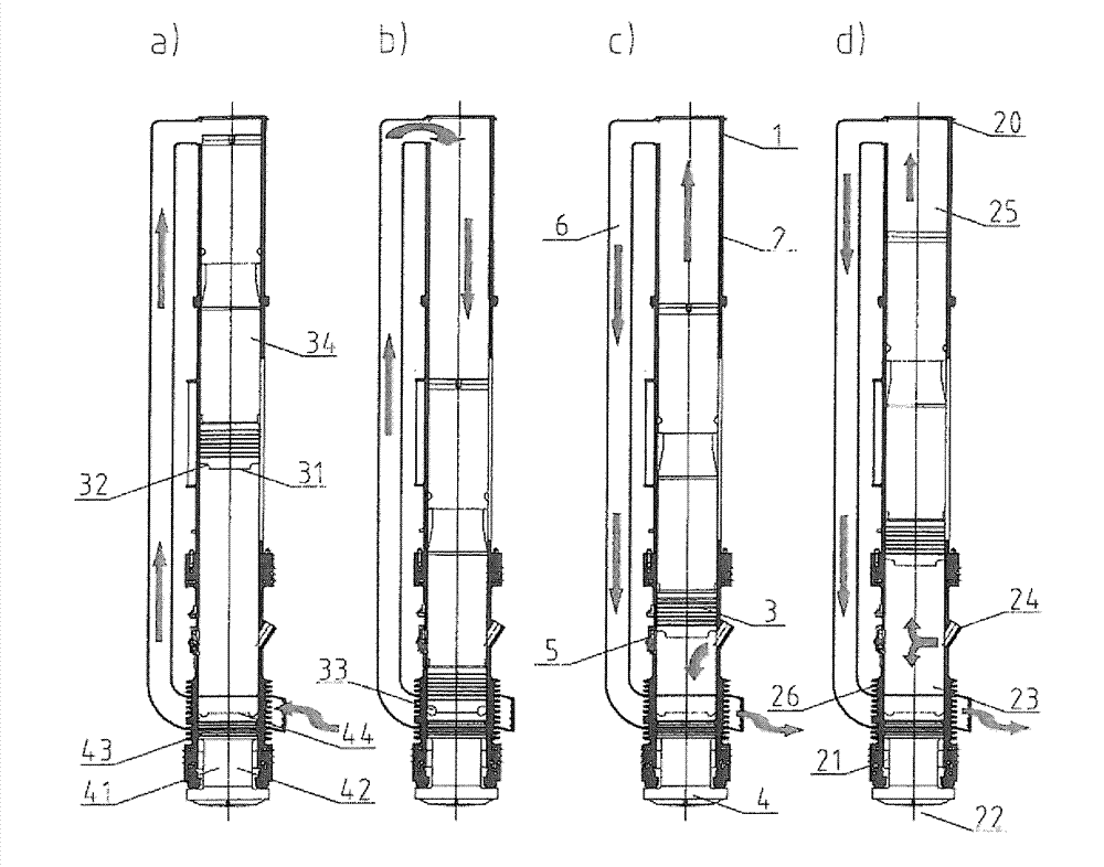
[0012] The rammer device chosen as exemplary embodiment is designed as a diesel rammer 1 . The diesel rammer 1 has a cylinder 2 which is open on one side and which can actually have a length of 5 to 10 meters and a diameter of 0.5 to 1 meter. The cylinder 2 is closed on its upper side by a cover plate 20 . A piston 3 is displaceably arranged in the cylinder 2 . A tamper block 4 coaxial therewith engages displaceably in the open lower end of the cylinder 2 . Arranged on the open lower end 22 of the cylinder 2 is an annular bearing unit 21 , in which a central shaft section 41 of the tamper block 4 is guided, said central shaft section having an angle relative to the cylinder 2 . Outer diameter with reduced inner diameter.

[0013] A striking plate 42 located below the cylinder 2 is integrally formed onto the lower end of the shaft section 41 , whose outwardly aligned, bottom-protruding border surface is in contact with the pile to be pressed in during operation, such as a sh...


PUM


Abstract

The invention relates to a tamping device, particularly to a diesel tamping device. The tamping device is provided with a cylinder having a movably supported piston therein and a tamping block arranged under the piston during the operating state, wherein a working cavity is limited in the axial direction between the end face of the tamping block inside the cylinder and the end face of the piston. With the arranged fuel jet apparatus, the fuel with regulated amount can be led to the working cavity. The cylinder (2) is sealed via a cover plate (20) at its upper side face opposite to the tamping block (4). A replacing chamber is arranged between the cover plate (20) and the piston (3) as well as between the piston (3) and the cover plate (20) when the phase step height of the piston (3) is at the maximum degree. The replacing chamber is connected with the air cooling apparatus applicable to the tamping device (1).

Description

technical field [0001] The invention relates to a rammer, in particular a diesel rammer according to the preamble of claim 1 . Background technique [0002] Such tamping devices such as diesel rammers, also known as diesel hammers, are used especially in the construction industry for laying all kinds of piles, such as concrete columns (Betonpfeiler), steel beams (Eisenträger), Sheet pile wall elements (Spundwandelements) or similar objects are driven into the foundation. During start-up of such a ramming device, the piston in the cylinder is pulled upwards by means of a release device and released at a defined height so that it falls downwards under the force of gravity. The fuel pump is actuated when the piston is lowered, so that fuel is delivered into the working chamber of the cylinder of the ramming device. [0003] By the downward movement of the piston in the cylinder of the ramming device, the air located in the working chamber of the cylinder is compressed and hea...

Claims


Application Information

Patent Timeline
Patent Type & Authority Applications(China)
IPC IPC(8): E02D7/12
CPCE02D7/125E02D3/061
Inventor M.海歇尔
Owner DELMAG
Learn More