
Network flow control system and network flow control method

A network flow and control system technology, applied in the field of network flow control and network flow control system, can solve problems such as packet burst, ingress P2P bandwidth is not controlled, and link egress is reduced

Inactive Publication Date: 2013-02-27
ZICT TECH CO LTD
View PDF4 Cites 20 Cited by
  • Summary
  • Abstract
  • Description
  • Claims
  • Application Information

AI Technical Summary

Problems solved by technology

[0005] (1) The TCP (Transmission Control Protocol, Transmission Control Protocol) protocol stack or P2P client will detect network packet loss and start packet retransmission, resulting in subsequent packet bursts;
[0006] (2) This method only reduces the P2P bandwidth of link egress, but the bandwidth of ingress P2P is not controlled

Method used


Image

  • Network flow control system and network flow control method
  • Network flow control system and network flow control method
  • Network flow control system and network flow control method

Examples


Embodiment Construction

[0035] In order to understand the above-mentioned purpose, features and advantages of the present invention more clearly, the present invention will be further described in detail below in conjunction with the accompanying drawings and specific embodiments. It should be noted that, in the case of no conflict, the embodiments of the present application and the features in the embodiments can be combined with each other.

[0036] In the following description, many specific details are set forth in order to fully understand the present invention. However, the present invention can also be implemented in other ways different from those described here. Therefore, the protection scope of the present invention is not limited by the specific details disclosed below. EXAMPLE LIMITATIONS.

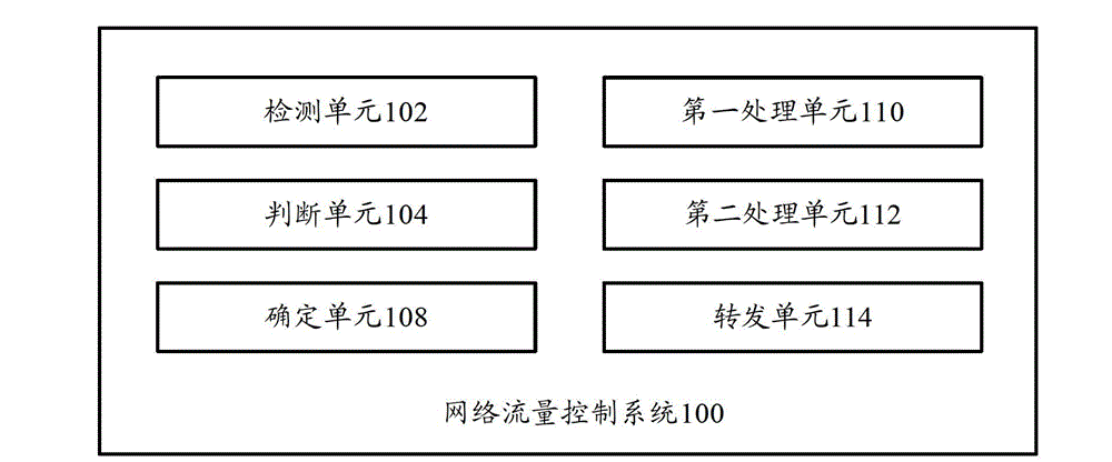
[0037] figure 1 A block diagram of a network traffic control system according to an embodiment of the present invention is shown.

[0038] Such as figure 1 As shown, the network traffic control sy...


PUM


Abstract

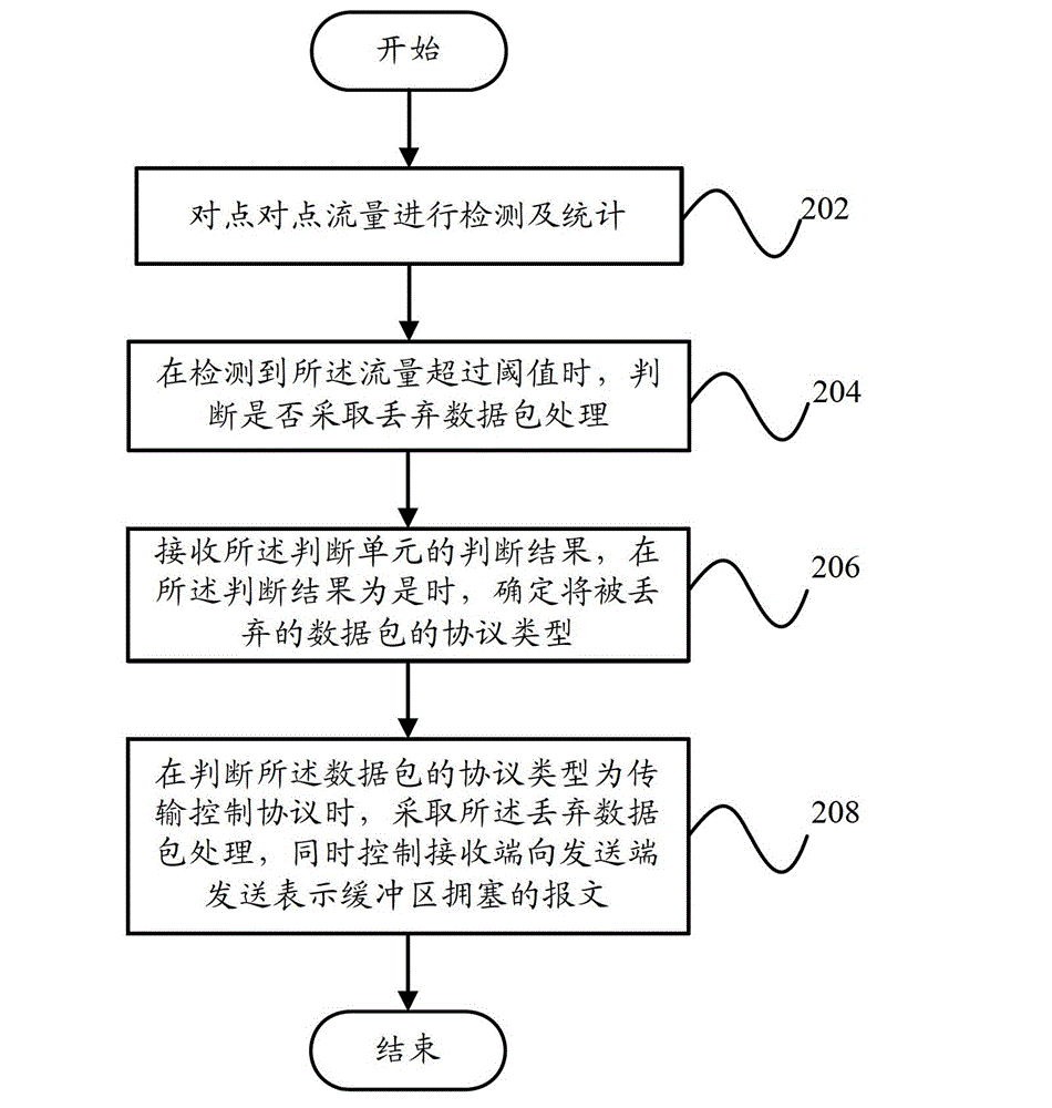
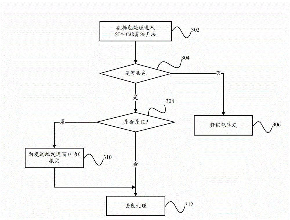
The invention provides a network flow control system which comprises a detecting unit, a judging unit, a determining unit and a first processing unit, wherein the detecting unit is used for detecting and counting point-to-point flows; the judging unit is used for judging whether an operation of discarding a data packet is taken when detecting that the flows exceed a threshold; the determining unit is used for receiving a judging result of the judging unit and determining a protocol type of the discarded data packet when judging that the operation of discharging the data packet is taken; and the first processing unit is used for taking the operation of discarding the data packet when judging that the protocol type of the data packet is a transition control protocol, and controlling a receiving end to send a message indicating buffer region congestion to a sending end. Correspondingly, the invention also provides a network flow control method. According to the technical scheme provided by the invention, when the flows exceed the threshold, while the operation of discarding the data packet is taken, the message indicating the buffer region congestion is sent to the sending end, so that the sending end knows that the receiving end is congested, and can be used for actively reducing the message sending rate, and ensuring that the inlet bandwidth is reduced while the outlet bandwidth is reduced.

Description

technical field [0001] The present invention relates to the field of network technology, in particular to a network flow control system and a network flow control method. Background technique [0002] With the development of Internet technology, P2P (Point to Point, peer-to-peer) technology develops rapidly and has more and more applications. While P2P prospers the Internet, it also consumes a large amount of Internet bandwidth. At present, P2P traffic accounts for more than 50% of the network. Due to the flood of P2P downloads on some networks, daily network applications such as HTTP web browsing and email sending and receiving are directly affected, causing users to be dissatisfied with operators. Operators respond to the rapid increase in Internet traffic by expanding network capacity, but the network built with huge investment will still reduce network availability due to network congestion caused by P2P, which affects the quality of telecommunications services. [000...

Claims


Application Information

Patent Timeline
IPC IPC(8): H04L12/801H04L12/823H04L1/18H04L47/32
Inventor 李双彬
Owner ZICT TECH CO LTD
Learn More