
High-power factor constant-current drive circuit and constant-current device

A high power factor, constant current drive technology, applied in output power conversion devices, lamp circuit arrangements, lighting devices, etc., can solve the problems of complex current sampling accuracy and inaccuracy in the power switch tube drive circuit, and ensure constant current. Control accuracy, reduce drive loss, and improve the effect of adjustment accuracy

Active Publication Date: 2013-02-27
HANGZHOU SILAN MICROELECTRONICS
View PDF3 Cites 14 Cited by
  • Summary
  • Abstract
  • Description
  • Claims
  • Application Information

AI Technical Summary

Problems solved by technology

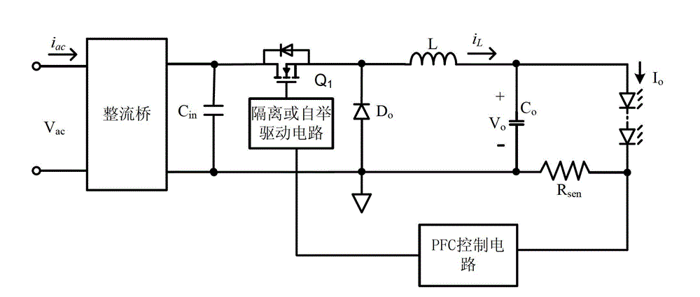
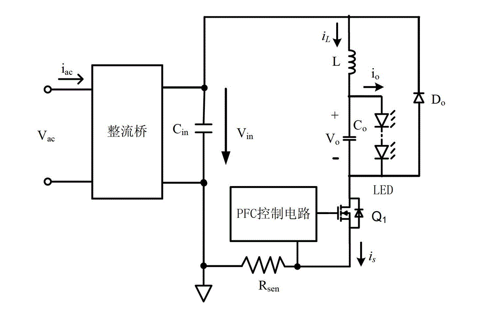
[0006] The technical problem to be solved by the present invention is to provide a high power factor constant current drive circuit and constant current device, which can solve the problems of complex power switch tube drive circuit and inaccurate current sampling accuracy in the conventional Buck type high power factor constant current drive circuit

Method used


Image

  • High-power factor constant-current drive circuit and constant-current device
  • High-power factor constant-current drive circuit and constant-current device
  • High-power factor constant-current drive circuit and constant-current device

Examples


Embodiment Construction

[0070] The present invention will be further described below in conjunction with specific embodiments and accompanying drawings, but the protection scope of the present invention should not be limited thereby.

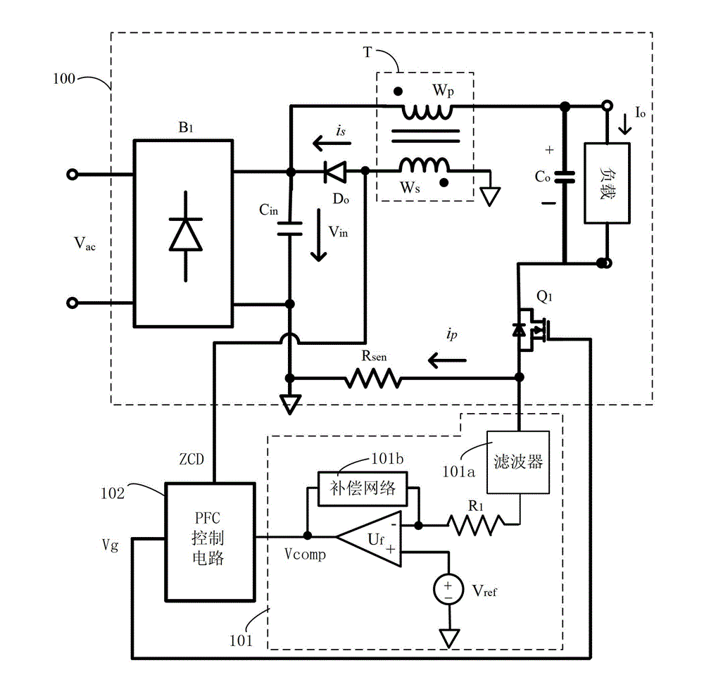
[0071] refer to image 3 , image 3 A schematic diagram of the constant current device of this embodiment is shown, and the constant current device includes a high power factor constant current drive circuit 100 and a control circuit for controlling it. Wherein, the high power factor constant current drive circuit 100 at least includes a rectifier bridge B1, an input capacitor Cin, an output diode Do, a transformer T, a power switch tube Q1, a current detection circuit Rsen and an output capacitor Co; the control circuit includes a load current control circuit 101 and A power factor correction (PFC) control circuit 102 .

[0072] Further, the input terminal of the rectifier bridge B1 is connected to the AC power supply Vac, the positive output terminal of the rectifi...


PUM


Abstract

The invention provides a high-power factor constant-current drive circuit and a constant-current device. The constant-current drive circuit comprises a rectifier bridge, an input capacitor, an output diode, a transformer, an output capacitor and a power switch tube, wherein the first end and the second end of the input capacitor are respectively connected with the positive and negative output ends of the rectifier bridge; the negative pole of the output diode is connected with the first end of the input capacitor; the same-polarity end of the primary winding of the transformer is connected with the first end of the input capacitor, the different-polarity end of the secondary winding of the transformer is connected with the positive pole of the output diode, and the same-polarity end of the secondary winding is connected to the ground; the first end of the output capacitor is connected with the different-polarity end of the primary winding; and the first power end of the power switch tube is connected with the second end of the output capacitor, the second power end of the power switch tube is connected to the ground through a current detection circuit, and the control end of the power switch tube receives an externally input drive signal. The high-power factor constant-current drive circuit and the constant-current device which are provided by the invention can solve the problems of complex power switch tube drive circuit and low current sampling accuracy of the conventional Buck type high-power factor constant-current drive circuit.

Description

technical field [0001] The invention relates to a high power factor constant current driving circuit and a constant current device. Background technique [0002] At present, there are nonlinear components and energy storage components in most electrical equipment, which will seriously distort the input AC current waveform, resulting in a very low input power factor at the grid side. In order to meet the harmonic requirements of the international standard IEC61000-3-2, it must Add power factor correction (PFC) devices to electrical equipment. [0003] Traditional active power factor correction circuits generally adopt boost (Boost) topology, buck-boost (Buck-boost) topology or step-down (Buck) topology. Among them, the Boost topology has the characteristics of easy control, simple driving, switching operation in the entire power frequency cycle, and the power factor of the input current can be close to 1. But the Boost circuit has the disadvantage of high output voltage, an...

Claims


Application Information

Patent Timeline
IPC IPC(8): H02M3/28H02M3/157H02M1/42H05B37/02
CPCY02B70/126Y02B70/10
Inventor 谢小高叶美盼吴建兴
Owner HANGZHOU SILAN MICROELECTRONICS
Learn More