Design method of cabinet power strip jacks

A technology of power strip and design method, which is applied to circuits, electrical components, parts of connecting devices, etc., can solve the problems of power strip burnout safety, hidden dangers, etc., to avoid potential safety hazards and achieve the effect of redundancy

Inactive Publication Date: 2013-02-27
LANGCHAO ELECTRONIC INFORMATION IND CO LTD
View PDF4 Cites 0 Cited by
  • Summary
  • Abstract
  • Description
  • Claims
  • Application Information

AI Technical Summary

Problems solved by technology

[0003] However, in the process of using the power strip, users are accustomed to the principle of proximity, and plug in the power supply sequentially from top to bottom or from bottom to top, so that it is easy to plug multiple power cords into the same road, resulting in multiple power cords. The machine (several power supplies work, and the remaining few are redundant) loses its original redundancy function, and the load is too large during use, causing the power strip to burn out and causing safety hazards

Method used


Image

  • Design method of cabinet power strip jacks
  • Design method of cabinet power strip jacks

Examples


Embodiment

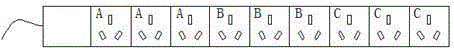
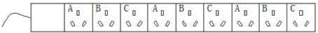
[0014] Using the design method provided by the present invention, take the design of a three-way cabinet power strip jack as an example. The three lines are A, B, and C respectively.

[0015] The method avoids plugging too many power lines into the same road during use through the improved design of different roads of adjacent jacks, and avoids potential safety hazards that may be caused by excessive use load.


PUM


Abstract

The invention provides a design method of cabinet power strip jacks, which is characterized in that adjacent jacks are designed into different circuits in an improvement design, jacks of an original cabinet power strip are arranged in a cross way, and additionally, a circuit board inside the power strip is correspondingly changed to support the cross arrangement of the jacks. According to the method, the habit of a user is respected well, the load is effectively distributed, so that the redundancy of a multi-power machine is realized well, and additionally, potential safety hazards caused by excessive working load are avoided.

Description

technical field [0001] The invention relates to the field of sockets, in particular to a design method for sockets of power sockets in cabinets. Background technique [0002] The cabinet power strip is a power access device specially used to supply power to the machines and equipment in the cabinet. Because the machines in the cabinet have special requirements for the power current, generally speaking, the current is larger than the usual one. For safety reasons Therefore, it is very important for the user to balance the various jacks on the utility power strip. [0003] However, in the process of using the power strip, users are accustomed to the principle of proximity, and plug in the power supply sequentially from top to bottom or from bottom to top, so that it is easy to plug multiple power cords into the same road, resulting in multiple power cords. The machine (several power supplies are working, and the remaining few are redundant) loses its original redundancy funct...

Claims


Application Information

Patent Timeline
IPC IPC(8): H01R13/10H01R13/66
Inventor 汪佳
Owner LANGCHAO ELECTRONIC INFORMATION IND CO LTD
Why Eureka
Try Eureka