
Motorcycle-chain protecting clamp and installing structure thereof

A mounting structure and technology for motorcycles, applied to bicycle accessories, transportation and packaging, bicycle auxiliary equipment, etc., can solve problems such as difficult assembly, easy loosening of the front end, and poor fit of the chain, and achieve easy structural assembly, simple and novel structure, Avoid Poor Positioning Effects

Active Publication Date: 2013-02-27
LONCIN MOTOR
View PDF5 Cites 3 Cited by
  • Summary
  • Abstract
  • Description
  • Claims
  • Application Information

AI Technical Summary

Problems solved by technology

[0003] The name in the prior art is "motorcycle chain guard", and the Chinese utility model patent No. 20620112068.X discloses a motorcycle chain guard. The inside of the chain guard is provided with a corresponding mounting hole on the flat fork. Two rubber positioning bosses, the positioning boss is composed of a transition section and a spherical head, the transition section and the spherical head are integrally structured, the diameter of the spherical head is slightly larger than the diameter of the mounting hole of the flat fork, and the diameter of the transition section is slightly smaller than the diameter of the mounting hole of the flat fork. Utilizing the self-elasticity of the rubber, the positioning boss on the guard card can be pressed into the mounting hole on the main body of the flat fork with a little force during installation, and a relatively large force is required to withdraw it. This utility model solves the problem of the chain The guard card is installed by screws, and the mounting screw is exposed outside the chain guard card, which has the disadvantages of contact and friction with the chain
However, by the disclosure of the invention attached image 3 , 4 It can be seen that the front end of the motorcycle chain guard is set on the flat fork, and the rear end is connected with the positioning hole on the flat fork through the positioning boss. This structure has the following shortcomings: one is that the front end of the motorcycle chain guard is set on the On the flat fork, after long-term use, there will be a gap between the motorcycle chain guard and the flat fork, so it will become loose and the positioning effect will be poor; the second is to use the rubber positioning boss to connect with the positioning hole on the flat fork for positioning. When the rubber is soft, reliable positioning cannot be achieved. At the same time, the rubber positioning boss is also easily damaged. When the rubber is hard, due to the interference fit between the spherical head and the positioning hole, assembly is difficult, and it is easily deformed and scrapped.
But this invention patent also has the following deficiencies: the one, because the front end arc of motorcycle chain guard card is enclosed within on the shaft sleeve outer circle of motorcycle flat fork, the cooperation of motorcycle chain guard card and flat fork will be difficult after long-term use There is a gap, so there will be looseness, especially the chain guard is made of elastic material, so the positioning effect is even worse; second, when the motorcycle chain guard is installed, the front end is set on the motorcycle flat fork, and the tail passes through the set hanging hole Positioning after hooking with the lugs on the horizontal tube, this positioning method only uses one point positioning, the reliability and stability of positioning are poor, and the motorcycle chain guard is also easy to deform
The Chinese invention patent named "Motorcycle Chain Guard and Flat Fork Combination" with patent number 209202069608 discloses a combination of motorcycle chain guard and flat fork. On the top, the rear end is fixed on the fork by bolts. The disadvantage is that the chain guard is fixed by one-point positioning, and the front end is easy to loosen, thus slipping off the fork. At the same time, the reliability and stability of one-point positioning are poor. At the same time, the chain guard of the motorcycle is also easy to deform; further, the chain guard of the invention adopts the structural form of tail bolt connection, and the chain guard needs to cross the flat fork horizontal tube to reach the support of the chain guard, so the length of the chain guard is relatively large , which increases the cost of using
The Chinese invention patent named "Motorcycle Chain Guard and Rear Fork Assembly" with the patent number of 209202069595 discloses a motorcycle chain guard and rear fork assembly. On the top, the rear end is fixed with the rear fork by bolts, and the front is positioned by the bump and the tube of the rear fork. The disadvantages are: first, because the bump is mushroom-shaped, and the diameter of the largest part of the bump head is slightly larger than the tube wall of the rear fork The diameter of the upper via hole, so the bump head and the via hole are an interference fit, which is difficult to assemble and is easily deformed and scrapped; second, the invention adopts two-point positioning, and there is also the possibility that the front end is easy to loose, thereby slipping off the rear fork, and at the same time The reliability and stability of the two-point positioning are relatively poor; the third is that the chain guard of the invention adopts the structural form of tail bolt connection, and the chain guard needs to cross the rear fork horizontal tube to reach the chain guard support, so the chain guard The length of the card is relatively large, which increases the cost of use
[0005] In summary, due to the deficiencies in the installation structure of the motorcycle chain guard in the prior art, there will be defects such as poor positioning, assembly deformation, and inability to cooperate well with the chain. Accurate, the guard card installation structure that can effectively shorten the length of the motorcycle chain guard card becomes necessary

Method used


Image

  • Motorcycle-chain protecting clamp and installing structure thereof
  • Motorcycle-chain protecting clamp and installing structure thereof
  • Motorcycle-chain protecting clamp and installing structure thereof

Examples


Embodiment Construction

[0024] Below in conjunction with accompanying drawing and embodiment the present invention will be further described:

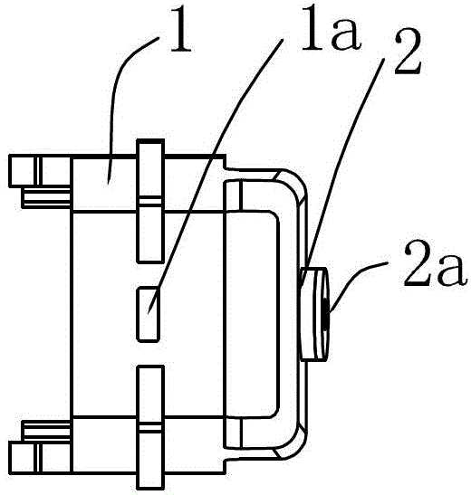
[0025] Such as figure 1 , figure 2 and image 3As shown, a motorcycle chain guard, the chain guard 1 is a "U"-shaped structure with a closed front end, a positioning hole 1a is provided at the front end of the chain guard 1, and a positioning hole 1a is provided on the middle side of the chain guard 1. The bridge 2 has a screw hole 2a on the positioning bridge 2, and the inner sides of the two feet of the chain guard 1 are respectively provided with hanging holes 3, and the hanging holes 3 are located at the rear of the chain guard 1.

[0026] See Figure 4 and Figure 5 : a motorcycle chain protection card installation structure, the chain protection card 1 is mounted on the motorcycle flat fork, the motorcycle flat fork includes flat fork side pipe 4 and flat fork horizontal pipe 5, because the motorcycle flat fork, flat fork The structure of the fork...


PUM


Abstract

The invention discloses a motorcycle-chain protecting clamp and an installing structure thereof. The chain protecting clamp is of a U-shaped structure with a front closed end, and the front end of the chain protecting clamp is provided with a positioning hole. The installing structure is characterized in that the chain protecting clamp is clamped on a motorcycle flat fork which comprises a flat-fork edge pipe and a flat-fork cross pipe; and the arc shape of the front end of the chain protecting clamp is sheathed at the front end of the flat-fork edge pipe in a positioning manner, the middle part of the chain protecting clamp is positioned at the side surface of the flat-fork edge pipe, and the rear end of the chain protecting clamp is positioned at the flat-fork cross pipe. The invention has the advantages that the motorcycle-chain protecting clamp is designed to be installed with the flat fork, and three-point positioning can be realized, so that the defects of improper positioning, assembling deformation and incapability of good matching with the chain in the prior art are avoided, easy structural assembly and accurate positioning are realized, the length of the motorcycle-chain protecting clamp can be effectively shortened, and the cost is reduced.

Description

technical field [0001] The invention belongs to the technical field of motorcycles, and in particular relates to a motorcycle chain guard clip and its installation structure. Background technique [0002] The motorcycle chain is used to transmit the output power of the engine to the rear wheel to drive the vehicle. One end of the chain is installed on the driving sprocket, and the other end is installed on the driven sprocket of the rear wheel. There is a flat fork between the driving sprocket and the driven sprocket, and the left side of the flat fork is located in the chain and is very close to the upper and lower chains. The nature of the chain transmission determines that the chain must have a certain amount of slack, and the chain will elongate and fall after being used for a period of time, thereby contacting the flat fork and generating friction, which will damage the chain and reduce the service life. In order to prevent friction between the chain and the chain fork...

Claims


Application Information

Patent Timeline
Patent Type & Authority Applications(China)
IPC IPC(8): B62J23/00
Inventor 肖嘉陈灏
Owner LONCIN MOTOR
Learn More