
Passenger train vacuum toilet

A technology of vacuum toilet and vacuum set, applied in railway car body parts, sanitary equipment, transportation and packaging, etc., can solve the problems of large compressed air consumption, large compressed air flow, complicated control system, etc., and achieves simple structure and economical efficiency. Compressed air, noise reduction effect

Active Publication Date: 2015-09-30
JIANGSU CRRC ENVIRONMENT CO LTD
View PDF6 Cites 2 Cited by
  • Summary
  • Abstract
  • Description
  • Claims
  • Application Information

AI Technical Summary

Problems solved by technology

The vacuum holding type dirt tank keeps vacuum all the time, and the compressed air consumption is large and the noise is louder every time the vacuum is established; the online pipeline requires a fast speed for each vacuum establishment, so the compressed air flow is required to be large and the noise is relatively large; the general push-pull type Positive pressure and negative pressure are required to control the discharge of pollutants, and the control system is complex

Method used


Image

  • Passenger train vacuum toilet
  • Passenger train vacuum toilet

Examples


Embodiment 1

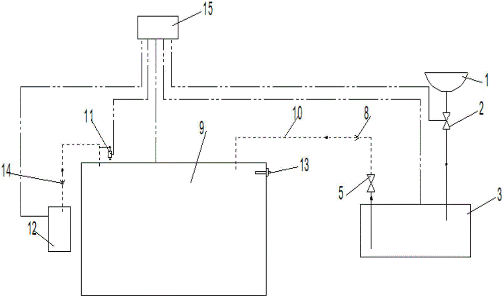
[0018] as attached figure 1 As shown, a vacuum toilet collection device for passenger trains mainly includes a vacuum toilet 1, a vacuum intermediate transition box 3, a dirt terminal collection box 9, a vacuum generating device 12, a PLC controller 15, a vacuum switch 11, a vacuum toilet 1 and a vacuum intermediate The transition box 3 is connected through a pipeline provided with a discharge control valve 2, and the vacuum intermediate transition box 3 is connected with the dirt terminal collection box 9 through a transmission pipeline 10, and the transmission pipeline 10 is provided with a first one-way valve 8, Transmission control valve 5, the transmission control valve 5 is connected to one end of the vacuum intermediate transition box 3, the dirt terminal collection box 9 is connected to the vacuum generating device 12 through a pipeline provided with a second one-way valve 14, the vacuum switch 11 is connected to the dirt terminal The collection box 9 is connected, the...

Embodiment 2

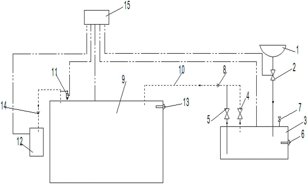
[0020] combine figure 2 , a vacuum toilet collection device for passenger trains, the transmission pipeline 10 is also provided with a vacuum transmission control valve 4, the vacuum transmission control valve 4 is connected to one end of the vacuum intermediate transition box 3, and the transmission control valve 5 is connected in parallel with the vacuum transmission control valve 4. The vacuum intermediate transition box 3 is provided with a vent valve 7, a liquid level sensor I6, and the liquid level sensor I6 and the vent valve 7 are connected to a PLC controller 15, and the PLC controller is a PLC programmable control unit. When the vacuum toilet 1 discharges sewage, the PLC controller 15 controls the discharge control valve 2 to open to allow the dirt to enter the vacuum intermediate transition box 3, otherwise the discharge control valve 2 is closed to prevent system vacuum leakage. After the vacuum intermediate transition box 3 receives the dirt once, that is, after ...


PUM


Abstract

The invention discloses a vacuum excrement collection device for a passenger train, which comprises a vacuum excrement collection device, a vacuum intermediate transition tank, a sewage terminal collection tank, a vacuum generation device, a PLC (programmable logic controller) and a vacuum switch, wherein the vacuum excrement collection device is connected with the vacuum intermediate transition tank which is connected with the sewage terminal collection tank, a first check valve and a transmission control valve are arranged on a conveying pipeline, the transmission control valve is connected with one end of the vacuum intermediate transition tank, one pipeline transports sewage and vacuum, the sewage terminal collection tank is connected with the vacuum generation device through a pipeline provided with a second check valve, the vacuum switch is connected with the sewage terminal collection tank which is provided with a liquid level sensor II, the PLC is connected with an electromagnetic valve I, an electromagnetic valve II, an electromagnetic valve III, the vacuum switch and the liquid level sensor II, one pipeline transports the sewage and the vacuum at the same time, compressed air is saved, the noises are reduced, the pipeline blockage is effectively reduced, and the pipeline is cleaned.

Description

technical field [0001] The invention relates to the technical field of passenger train toilets, in particular to a passenger train vacuum toilet used in passenger train toilets. Background technique [0002] At present, the vacuum toilets in the toilets of passenger trains generally adopt vacuum holding type, online type or push-pull type and the like. The vacuum holding type dirt tank keeps vacuum all the time, and the compressed air consumption is large and the noise is louder every time the vacuum is established; the online pipeline requires a fast speed for each vacuum establishment, so the compressed air flow is required to be large and the noise is relatively large; the general push-pull type Positive pressure and negative pressure are required to control the discharge of pollutants, and the control system is complex. Contents of the invention [0003] The purpose of the present invention is to solve the above-mentioned problems and deficiencies in the prior art; pr...

Claims


Application Information

Patent Timeline
Patent Type & Authority Patents(China)
IPC IPC(8): B61D35/00
Inventor 宋彬龙超王玉秋曲凯丁国严巾堪
Owner JIANGSU CRRC ENVIRONMENT CO LTD
Learn More