Centrifugal forming die and construction method for high-strength conical cement pole

A centrifugal molding and cement pole technology, which is used in the field of cement communication poles, conical cement poles, and cement lamp poles, can solve the problems of difficult control of the wall thickness of cement poles, dirty working environment, and poor quality of the inner wall, etc. The effect of secondary sealing process, high internal structure strength and smooth inner and outer surfaces

Active Publication Date: 2013-02-27
元工能源科技集团有限公司
View PDF7 Cites 23 Cited by
  • Summary
  • Abstract
  • Description
  • Claims
  • Application Information

AI Technical Summary

Problems solved by technology

In this process, because the inner hole of the product is not limited by the mold, the inner surface of the concrete grout is in a free state, and the excess grout is thrown out from both ends of the mold, making the working environment dirty. The inner surface is flowing, resulting in uneven wall thickness of the cement rod and poor quality of the inner wall
And this kind of centrifugal process is only limited to concrete molding with coarse aggregate. When the cement mortar without coarse aggregate is used to make cement rods, the existing process will cause the inner wall to collapse and the outer wall to sink.
In addition, due to the different diameters of the two ends of the cement rod, the centrifugal force generated by the cement mortar at both ends is also different during rotation. In the traditional horizontal centrifugal process, the cement mortar will continuously flow from the small end to the large end, making the wall thickness of the cement rod hard to control
Another thing is that the top of the product produced by this process is in the form of openings. In order to prevent rain erosion, it is necessary to make a cement head after it is made, which increases the process, and the secondary bonding of the head is not firm and easy to fall off.

Method used


Image

  • Centrifugal forming die and construction method for high-strength conical cement pole
  • Centrifugal forming die and construction method for high-strength conical cement pole
  • Centrifugal forming die and construction method for high-strength conical cement pole

Examples


Embodiment Construction

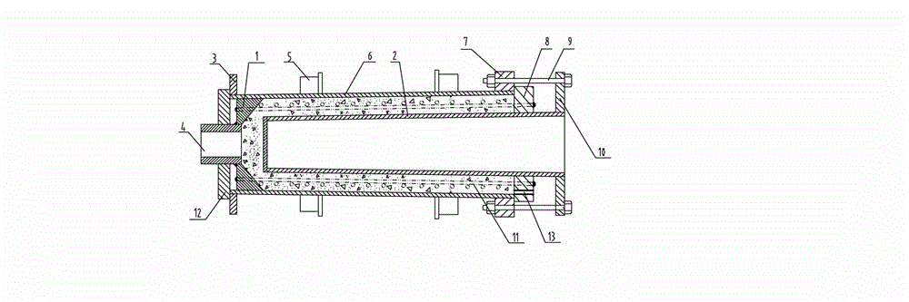
[0027] Such as figure 1 Shown, the centrifugal molding die of high-strength tapered cement rod of the present invention is characterized in that comprising cone-shaped outer mold 6, the cone-shaped internal mold 2 of concentric with this cone-shaped outer mold, and this cone-shaped inner mold The big-end flange plate 10 of the intima fixedly connected to the large-diameter end of the shape inner mold is sleeved on the large-end prestressed tension ring 8 on the large-diameter end of the cone-shaped inner mold 2, which is connected with the cone respectively. The outer mold large end flange plate 7 and the outer mold small end flange plate 3 fixedly connected to the large diameter end and the small diameter end of the cylindrical outer mold, and the mold cavity that is slidingly and sealingly connected with the small end inner hole of the tapered cylindrical outer mold End closure plate 1, a group of running wheels 5 fixedly connected to the outer surface of the cone-shaped out...


PUM


Abstract

The inventions belongs to the technical fields of manufacture of conical cement electric poles, cements communication poles and cement lamp poles and particularly relates to a centrifugal forming die and a construction method for a high-strength conical cement pole. The centrifugal forming die comprises a conical outer die, a conical inner die, an inner die large-end flange plate, a large-end prestress tensioning ring, an outer-die large-end flange plate, an outer-die small-end flange plate, a die cavity small-end closing plate, one group of running wheels, one group of bolt assemblies, a prestress locking nut, a mortar injecting port and an exhaust port, wherein the conical outer die, the conical inner die, the large-end prestress tensioning ring and the die cavity small-end closing plate form a closed annular die cavity; one group of large-end longitudinal rib inserting holes are formed in the large-end prestress tensioning ring; and one group of small-end longitudinal rib inserting holes are formed in the die cavity small-end closing plate. According to the centrifugal forming die and the construction method disclosed by the invention, the conical cement poles with the advantages of smooth inner and outer surfaces, high internal structural strength and uniformity in wall thickness can be produced. In addition, the wall thickness of the cement poles can be accurately controlled, so that the materials can be saved, the service strength of the pole bodies is ensured and the work environment of the field is improved.

Description

technical field [0001] The invention belongs to the technical field of manufacturing conical cement poles, cement communication poles and cement light poles. In particular, the invention relates to a centrifugal forming mold and a construction method of a high-strength conical cement rod. Background technique [0002] At present, the general method of manufacturing cement rods is mainly to use the mold as a single outer mold centrifugal molding process, that is: firstly put the prepared reinforcing rib skeleton into the outer mold, and then put the mixed concrete cement slurry into the outer mold , Place the mold on the centrifuge to rotate at high speed, so that the concrete loaded into the mold is rotated and centrifuged, so that the concrete is evenly distributed on the inner wall of the mold. Remove the mold from the centrifuge, steam curing after the concrete is solidified, and then cool and demould to complete the main production process. In this process, because the...

Claims


Application Information

Patent Timeline
Patent Type & Authority Applications(China)
IPC IPC(8): B28B21/80B28B21/82
Inventor 祁锦明
Owner 元工能源科技集团有限公司
Why Eureka
Try Eureka