Method for fabricating precast products and forming appliance

A molding device and manufacturing method technology, applied in the direction of manufacturing tools, ceramic molding machines, mold separation devices, etc., can solve the problems of uneconomical benefits, waste of steel, slow progress in construction time, etc., to simplify the construction process and strengthen the internal structure Strength, the effect of rapid mass-production manufacturing

Active Publication Date: 2009-04-08
RUNHORN PRETECH ENG CO LTD
View PDF3 Cites 0 Cited by
  • Summary
  • Abstract
  • Description
  • Claims
  • Application Information

AI Technical Summary

Problems solved by technology

[0002] Existing prefabricated parts (beams, columns, etc.) are widely used in general building construction projects, and the production of prefabricated parts is almost always erected on the building construction site with steel cables, steel cages and formwork. Then pour concrete to form prefabricated parts, and some beams and columns are prefabricated in the prefabrication factory, and then transported to the construction site of the building, and combined with the base or beams, columns, etc. by using the assembly construction method; the former method is used in building construction. When prefabricating beam pillars, it is necessary to pre-install and fix steel cables and steel cages at the base of each prefabricated beam pillar, and set up a fixed formwork before grouting, and it is necessary to wait until the concrete in the formwork is solidified. For the next project, the construction time will be slow, which will prolong the construction period of the building; and when using the latter method to apply prefabricated beams and pillars to the building construction, although the required prefabricated beams and columns can be prefabricated in the prefabrication factory, but because of Due to the production method, it not only wastes a lot of steel, but also the speed and efficiency of its production are very slow, which is not in line with economic benefits.

Method used


Image

  • Method for fabricating precast products and forming appliance
  • Method for fabricating precast products and forming appliance
  • Method for fabricating precast products and forming appliance

Examples


Embodiment Construction

[0073] After further description of the preferred embodiment of the present invention in conjunction with the following diagrams, it will become clearer.

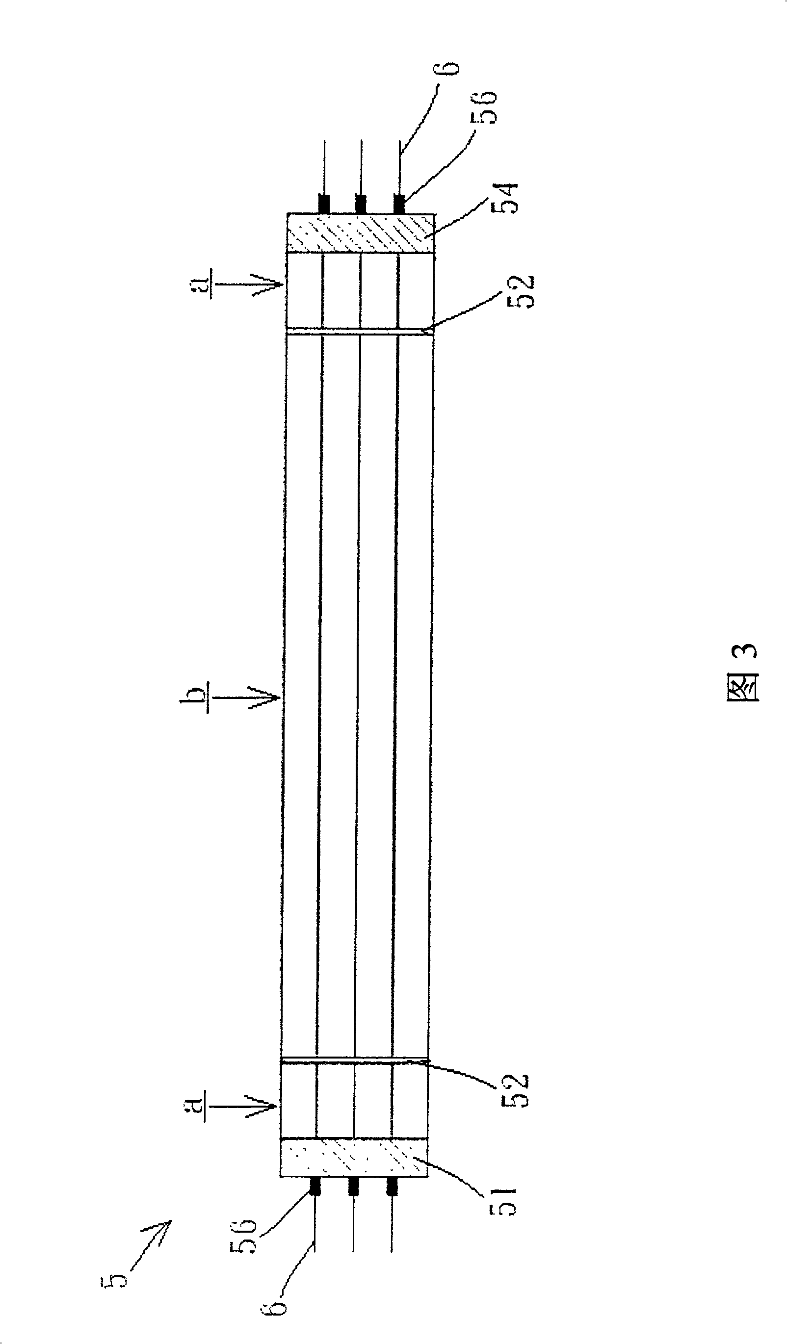
[0074] The present invention mainly uses different end molds to change the linear laying structure of steel cables inside the prefabricated part structure, so as to strengthen the structural strength of the prefabricated part structure and achieve the efficiency of rapid and mass production. Please refer to Figures 1A to 1C and Figure 1 at the same time. 2 is a schematic diagram of the appearance of the end mold body of the molding device of the present invention and a schematic diagram of the appearance of the connecting kit. It can be clearly seen from the figure that the end mold and some internal component structures used in the present invention include the front steel cable fixing Connecting end mold 51, linking kit 56, bolt 57, component size end mold 52, rear piece steel cable fixed end mold 54, wherein the connectin...


PUM


Abstract

The present invention relates to a production method of prefabricated component and its forming equipment. Said equipment includes the following several portions: a prefabricated bottom mould seat, a front wire rope fixed connection end mould, several connecting cover pieces, several bolts, one or several component size end moulds, a rear wire rope fixed connection end mould, a left side form and a right side form, in which on the front wire rope fixed connection end mould and on the rear wire rope fixed connection end mould respectively a horizontal wire-guiding groove is set and on the component size end mould a vertical wire-guiding groove is set. Besides, said invention also provides the concrete steps of said production method.

Description

technical field [0001] The present invention relates to a manufacturing method and its forming device, in particular to a preform manufacturing method and its forming device. A method for manufacturing prefabricated parts and a forming device thereof for improving the production efficiency of prefabricated concrete prefabricated parts. Background technique [0002] Existing prefabricated parts (beams, columns, etc.) are widely used in general building construction projects, and the production of prefabricated parts is almost always erected on the building construction site with steel cables, steel cages and formwork. Then pour concrete to form prefabricated parts, and some beams and columns are prefabricated in the prefabrication factory, and then transported to the construction site of the building, and combined with the base or beams, columns, etc. by using the assembly construction method; the former method is used in building construction. When prefabricating beam pilla...

Claims


Application Information

Patent Timeline
Patent Type & Authority Patents(China)
IPC IPC(8): B28B7/26B28B23/02
CPCB28B23/026B28B23/043
Inventor 尹衍梁吴子良刘俊磊
Owner RUNHORN PRETECH ENG CO LTD
Why Eureka
Try Eureka