
Robot integrated joint location detecting method based on double-rotation change coaxial design

A robot joint and resolver technology, applied in the field of robotics, can solve problems such as low algorithm accuracy, poor reliability, and failure of robot joints

Active Publication Date: 2013-02-27
BEIJING INSTITUTE OF TECHNOLOGYGY
View PDF5 Cites 10 Cited by
  • Summary
  • Abstract
  • Description
  • Claims
  • Application Information

AI Technical Summary

Problems solved by technology

[0004] After researching the existing technology, the inventors found that the robot joint of the permanent magnet synchronous motor in the prior art usually adopts the method of dividing the motor position by the reduction ratio n of the reducer when solving the joint rotation angle, To obtain the joint position, the algorithm for solving the joint position has low precision and poor reliability, and for this installation method, when the detection element on the motor side is damaged, the motor will be out of control and cause the joint failure of the robot

Method used


Image

  • Robot integrated joint location detecting method based on double-rotation change coaxial design
  • Robot integrated joint location detecting method based on double-rotation change coaxial design
  • Robot integrated joint location detecting method based on double-rotation change coaxial design

Examples


Embodiment Construction

[0015] In order to make the object, technical solution and advantages of the present invention clearer, the implementation manner of the present invention will be further described in detail below in conjunction with the accompanying drawings.

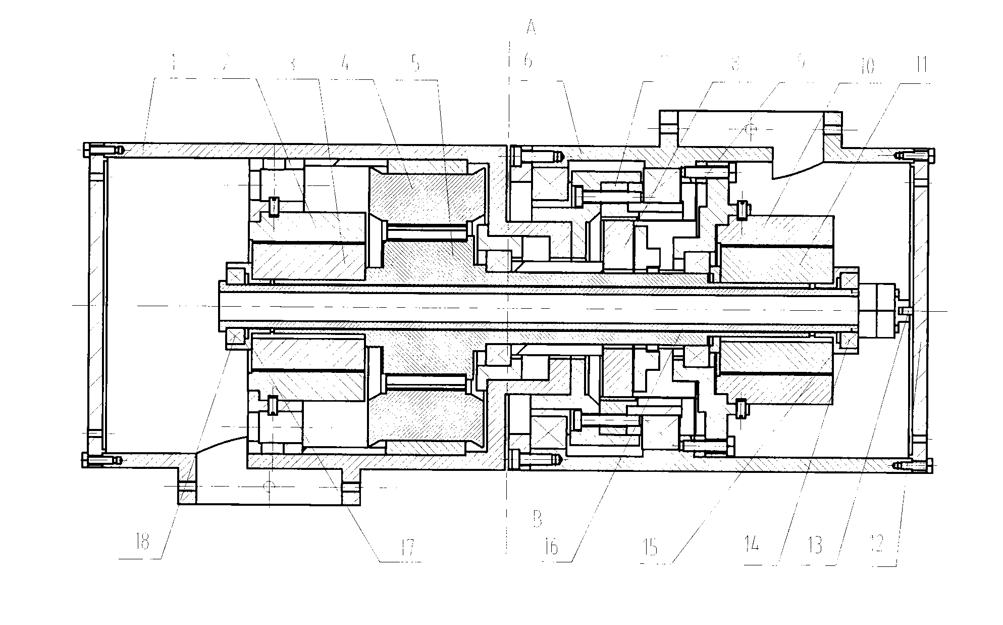
[0016] figure 1 A kind of robot joint based on the permanent magnet synchronous motor proposed by the present invention, the interior of the joint includes the following components: motor housing 1; motor side rotary transformer stator 2; motor side rotary transformer rotor 3; permanent magnet synchronous motor stator 4; permanent magnet synchronous motor stator 4; Magnetic synchronous motor rotor 5; joint output side casing 6; harmonic reducer steel wheel 7; harmonic reducer wave generator 8; harmonic reducer flexible wheel 9; joint output side resolver stator 10; joint output side resolver Rotor 11; joint right gear cover 12; hollow shaft positioning pin 13; motor bearing 14; bearing mount 15; motor main shaft 16; bearing mount 17; m...


PUM


Abstract

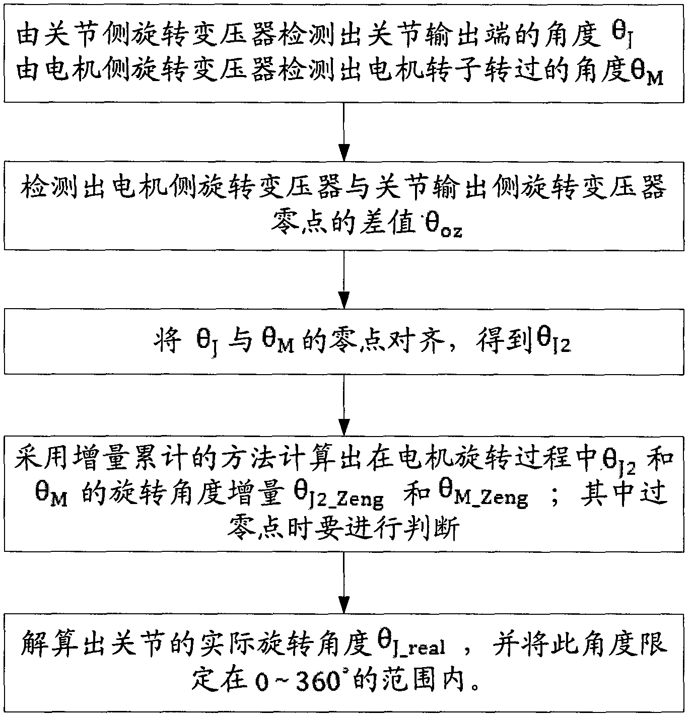
The invention discloses a robot integrated joint location detecting method based on double-rotation change coaxial design. The method comprises the following steps: firstly, determining a difference value between absolute zero points of rotary transformers on two sides; then, using an angel increment accumulation method to accumulate increments of an angle theta M measured at the rotary transformer on a motor side and an angle theta J2 measured at the rotary transformer on a joint side during the motor rotation, and obtaining the difference value through one angle minus the other, which is the actual rotation angle of the joint. At the same time, when calculating the angle increment, the moment of crossing the zero points is specially treated, that is to say, the maximum probable value between the angle difference values at the next moment and the last moment of the motor is obtained to be taken as the critical value for judgment according to the time difference value between the maximum rotating speed of the motor and the resolved angle of the rotary transformers.

Description

technical field [0001] The invention relates to the technical field of robots, in particular to a robot integrated joint position detection method based on a double-rotor coaxial design. Background technique [0002] With the development of integrated circuits, power electronics technology and AC variable speed drive technology, permanent magnet AC servo drive technology has achieved outstanding development. Compared with DC servo motors, permanent magnet AC servo motors have the following main advantages: brushless and commutation Therefore, it works reliably, has low maintenance and maintenance requirements, has good speed control characteristics, and is easy to improve the rapidity of the system. Permanent magnet synchronous motors based on permanent magnet AC servo drive technology can be applied to joints and other parts of robots. [0003] In the robot joint based on the permanent magnet synchronous motor, corresponding detection elements are required to detect the ro...

Claims


Application Information

Patent Timeline
Patent Type & Authority Applications(China)
IPC IPC(8): B25J17/02B25J19/00
Inventor 蒋志宏黄强李丹凤李辉
Owner BEIJING INSTITUTE OF TECHNOLOGYGY
Learn More