High-pressure pump

A technology for high-pressure pumps and pump components, applied in the field of high-pressure pumps, radial or in-line plunger pumps, can solve the problems of fluid dynamic characteristics deterioration, drive mechanism damage, friction increase, etc., to achieve improved rolling characteristics and fluid flow dynamic effect

Active Publication Date: 2015-04-08
ROBERT BOSCH GMBH
View PDF6 Cites 0 Cited by
  • Summary
  • Abstract
  • Description
  • Claims
  • Application Information

AI Technical Summary

Problems solved by technology

However, this also results in the disadvantage that the friction between the roller and the roller shoe is increased due to the roller configuration different from the cylindrical shape, because the hydrodynamic behavior is deteriorated due to the larger gap between the roller and the roller shoe
This makes it more difficult for the rollers to roll smoothly, which can also lead to damage to the drive mechanism under certain circumstances

Method used


Image

  • High-pressure pump
  • High-pressure pump

Examples


Embodiment Construction

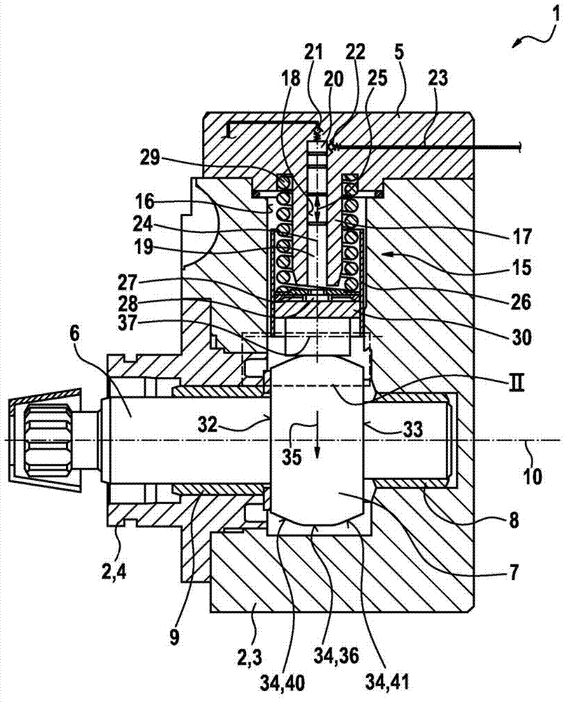
[0016] figure 1 A high-pressure pump 1 according to one embodiment of the present invention is shown in schematic axial section. In particular, the high-pressure pump 1 can be designed as a radial pump or as an in-line piston pump. The high-pressure pump 1 is particularly suitable as a fuel pump of a fuel injection system for an air-compressed self-igniting internal combustion engine. A preferred application of the high-pressure pump 1 is in fuel injection systems provided with a fuel distribution rail, a so-called common rail, which stores diesel fuel under high pressure. However, the high-pressure pump 1 according to the invention is also suitable for other applications.

[0017] The high-pressure pump 1 has a multi-part pump housing 2 . The pump housing 2 here comprises a housing part 3 and a flange 4 connected to the housing part 3 . Furthermore, a cylinder head 5 is provided, which is connected to the housing part 3 .

[0018] A drive shaft 6 is arranged in the pump ...


PUM


Abstract

The invention relates to a high-pressure pump (1), which is used in particular as a radial or in-line piston pump for fuel injection systems of air-compressing, auto-igniting internal combustion engines, comprising a pump assembly (5) and a drive shaft (6), which comprises a cam (7) associated with the pump assembly (15). The pump assembly (15) has a roller shoe (30) and a roller (31) mounted in the roller shoe (30). The roller (31) rolls on a running face (34) of the cam (7). To this end, the cam (7) has eased areas (40, 41) on the running face (34) thereof. The eased areas (40, 41) ensure advantageous guidance of the roller (31) on the running face (34). The eased areas (40, 41) are needed in order to avoid edge loading. The fact that the eased areas are located on the camshaft and not on the roller (31) means that the hydrodynamics between the roller (31) and the roller shoe (30) can be perfected.

Description

technical field [0001] The present invention relates to high pressure pumps, especially radial or inline piston pumps. The invention relates in particular to the field of fuel pumps for compressed air, fuel injection devices of self-igniting internal combustion engines. Background technique [0002] A high-pressure pump for a fuel injection system of an internal combustion engine is known from DE 10 2005 046 670 A1. The known high-pressure pump has a pump housing in which a pump part is arranged, which includes a pump piston driven in a lifting motion by a drive shaft. The pump piston is guided displaceably in a cylindrical bore in a part of the pump housing and defines a pump working chamber in this bore. The pump piston is supported indirectly on the drive shaft via a cylindrically-surfaced push rod, wherein the push rod is guided displaceably in a bore in a part of the pump housing in the direction of the pump piston's longitudinal axis. The longitudinal axis of the pu...

Claims


Application Information

Patent Timeline
Patent Type & Authority Patents(China)
IPC IPC(8): F02M59/10F04B1/04F02M59/06F02M59/44F04B9/04
CPCF02M59/06F04B1/0439F02M59/102F04B9/042F04B1/0413F02M59/44
Inventor F·伯金A·真特M·格莱纳
Owner ROBERT BOSCH GMBH
Why Eureka
Try Eureka