
Wireless charging system

A technology of wireless charging and wireless transmission, applied in the field of electrical appliances, can solve problems such as reducing user experience, affecting user work and life, and high power consumption, achieving significant practical significance in production, enhancing product experience, and making work and life more convenient Effect

Inactive Publication Date: 2013-02-13
TIANJIN SAMSUNG OPTO ELECTRONICS +1
View PDF3 Cites 11 Cited by
  • Summary
  • Abstract
  • Description
  • Claims
  • Application Information

AI Technical Summary

Problems solved by technology

[0004] When people use mobile computers, mobile phones, tablet computers and other electrical appliances to connect to wireless routers, mobile computers, mobile phones, tablet computers and other electrical appliances need to transmit various data wirelessly with wireless routers, so they consume a lot of power. Seriously shorten the standby working time of mobile computers, mobile phones, tablet computers and other electrical appliances
In addition, when people go out to use electrical appliances such as mobile computers, mobile phones, tablet computers, and digital cameras, they are often unable to connect to the mains power supply, which will greatly reduce the working hours of these appliances and affect the next use of these appliances by users, thereby affecting affect the work and life of users, and seriously reduce the user's experience in using mobile computers, mobile phones, tablet computers and other electrical appliances

Method used


Image

  • Wireless charging system
  • Wireless charging system
  • Wireless charging system

Examples


Embodiment Construction

[0037] In order to enable those skilled in the art to better understand the solution of the present invention, the present invention will be further described in detail below in conjunction with the accompanying drawings and embodiments.

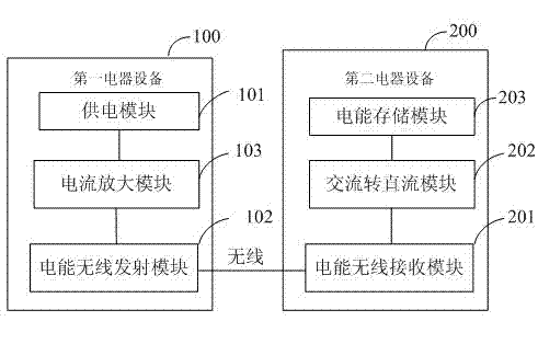
[0038] see figure 1 , the present invention provides a wireless charging system that utilizes the principle of magnetic resonance for charging, including: a first electrical device 100 for external charging and a second electrical device 200 that needs to be charged, wherein:

[0039] A first electrical device 100, which includes a power supply module 101 and a power wireless transmission module 102, wherein:

[0040] The power supply module 101 is used to output a DC current to the power wireless transmission module to drive the power wireless transmission module to work;

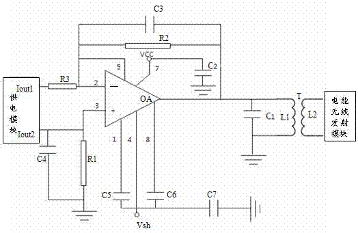
[0041] The electric energy wireless transmission module 102 is connected with the power supply module, and is used to generate electromagnetic waves vibrating according...


PUM


Abstract

The invention discloses a wireless charging system, comprising first electrical equipment for externally charging and second electrical equipment needing to be charged, wherein the first electrical equipment comprises a power supply module and a wireless electric energy transmitting module which are connected with each other; the second electrical equipment comprises a wireless electric energy receiving module, an AC (alternative current)-to-DC (direct current) module and an electric energy storing module; the wireless electric energy receiving module is connected with the wireless electric energy transmitting module in a wireless manner; the AC-to-DC module is connected with the wireless electric energy receiving module; and the electric energy storing module is connected with the AC-to-DC module, and is used for storing direct-current current output from the AC-to-DC module. The wireless charging system disclosed by the invention can conveniently and reliably charge various electrical devices, such as a mobile computer, a mobile phone, a flat computer, a digital camera and the like, in a wireless manner, thus guaranteeing that the working time of the electric devices can be prolonged, and bringing convenience to work and daily life of a user.

Description

technical field [0001] The invention relates to the technical field of electrical appliances, in particular to a wireless charging system. Background technique [0002] In recent years, with the improvement of people's living standards, electrical appliances such as computers, mobile phones, and tablet computers have become more and more popular. In work and life, people often use routers to connect these electrical appliances to the Internet to achieve convenient and fast data communication. [0003] With the increasing popularity of the Internet, routers have become an essential Internet access device for every family and public places. At the same time, people have higher and higher requirements on the multi-function of routers, and routers have developed from wired routers to more widely used wireless routers. [0004] When people use mobile computers, mobile phones, tablet computers and other electrical appliances to connect to wireless routers, mobile computers, mob...

Claims


Application Information

Patent Timeline
IPC IPC(8): H02J7/02H02J17/00H02J7/00H02J50/12
Inventor 刘宝杨尹熙正曹再铉
Owner TIANJIN SAMSUNG OPTO ELECTRONICS
Learn More