A switch cabinet grounding knife switch locking device

A technology of grounding knife switch and locking device, which is applied in the direction of electric switches, electrical components, circuits, etc., can solve the problems that the incoming cable cannot be changed to the maintenance state, cannot judge whether the cable line is live, and increases the operating time of the operator, etc., to achieve The effect of avoiding the failure of the locking device, avoiding the accident of live closing and grounding knife switch, and avoiding the accident of misoperation

Inactive Publication Date: 2016-04-27
STATE GRID CORP OF CHINA +3
View PDF4 Cites 0 Cited by
  • Summary
  • Abstract
  • Description
  • Claims
  • Application Information

AI Technical Summary

Problems solved by technology

[0002] The grounding knife of the inlet and outlet interval of the medium voltage switchgear is normally on the line side, and after the inlet and outlet switch is opened, the grounding knife is automatically unlocked, especially in the outdoor ring network cabinet. After the indicator light of the display fails, it is easy for the operator to mistakenly close the grounding knife, resulting in three-phase grounding of the line.
There are currently three solutions: one is to remove the locking device and block the operating hole of the grounding knife switch, which will inevitably cause the incoming cable to be unable to be changed to the maintenance state after a power failure; The attention of the operator, but in the case of a live display failure, it is impossible to judge whether the cable line is live, and there are also hidden dangers; the third is to lock the operating hole of the grounding knife switch with an open lock, which increases the operating time of the operator. It is difficult to function when the live display fails

Method used


Image

  • A switch cabinet grounding knife switch locking device
  • A switch cabinet grounding knife switch locking device

Examples


Embodiment Construction

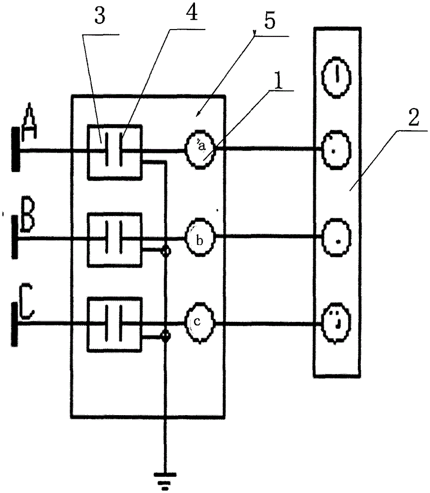
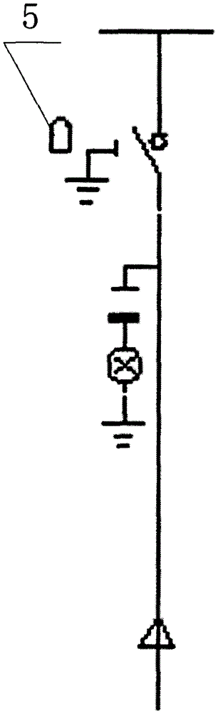
[0009] exist figure 1 and figure 2 Among them, the present invention provides a switch cabinet grounding knife switch locking device, which includes a locking device body 5, the locking device body 5 is provided with a three-phase electromagnetic generating device 1, and the joint of the three-phase electromagnetic generating device 1 is provided with a sealing Insulation protective cover, one side of the three-phase electromagnetic generator 1 is connected to the power supply 2, and the other end is connected to the grounding switch 3, the three-phase electromagnetic generating device 1 is linked with the baffle 4 of the operation hole of the grounding switch 3, the three-phase electromagnetic The connecting rod of the generator 1 drives the baffle 4 to limit the movement. When the cable line is electrified, the three-phase electromagnetic generator 1 drives the baffle 4 to move to close the operation hole of the grounding knife switch 3, and the grounding knife switch 3 sto...


PUM


Abstract

The invention discloses a locking device of a grounding knife switch of a switch cabinet. The locking device of the grounding knife switch of the switch cabinet comprises a locking device body (5), wherein the locking device body (5) is provided with a three-phase electromagnetic generating device (1); one side of the three-phase electromagnetic generating device (1) is connected with a power supply (2), and the other end of the three-phase electromagnetic generating device (1) is linked with a grounding knife switch (3); the three-phase electromagnetic generating device (1) is linked with a baffle plate (4) of an operating hole in the grounding knife switch (3); a connecting rod (5) of the three-phase electromagnetic generating device (1) drives the baffle plate (4) to perform moving limit; when an electric cable is electrified, the three-phase electromagnetic generating device (1) drives the baffle plate (4) to move to close the operating hole in the grounding knife switch (3), and the grounding knife switch (3) stops operating; and when the electric cable is not electrified, the three-phase electromagnetic generating device (1) drives the baffle plate (4) to move to close the operating hole in the grounding knife switch (3), and the grounding knife switch (3) begins to operate.

Description

technical field [0001] The invention relates to a locking device for a grounding knife switch of a switch cabinet. Background technique [0002] The grounding knife of the inlet and outlet interval of the medium voltage switchgear is normally on the line side, and after the inlet and outlet switch is opened, the grounding knife is automatically unlocked, especially in the outdoor ring network cabinet. After the indicator light of the display fails, it is easy for the operator to close the grounding knife by mistake, resulting in three-phase grounding of the line. There are currently three solutions: one is to remove the locking device and block the operating hole of the grounding knife switch, which will inevitably cause the incoming cable to be unable to be changed to the maintenance state after a power failure; The attention of the operator, but in the case of a live display failure, it is impossible to judge whether the cable line is live, and there are also hidden dange...

Claims


Application Information

Patent Timeline
Patent Type & Authority Patents(China)
IPC IPC(8): H01H9/20
Inventor 陈旭马筱亮李胜华王进
Owner STATE GRID CORP OF CHINA
Why Eureka
Try Eureka