
Substrate containing alignment layer and manufacture method thereof and display device thereof

A manufacturing method and technology of alignment layer, which are applied in the directions of instruments, nonlinear optics, optics, etc., can solve the problems affecting the adhesion degree of the frame sealant 14 and the substrate, display defects, and inability to realize the effect of narrow frame design, and achieve the realization of the design effect. effect, effect of reducing distance

Inactive Publication Date: 2015-07-01
BOE TECH GRP CO LTD
View PDF5 Cites 0 Cited by
  • Summary
  • Abstract
  • Description
  • Claims
  • Application Information

AI Technical Summary

Problems solved by technology

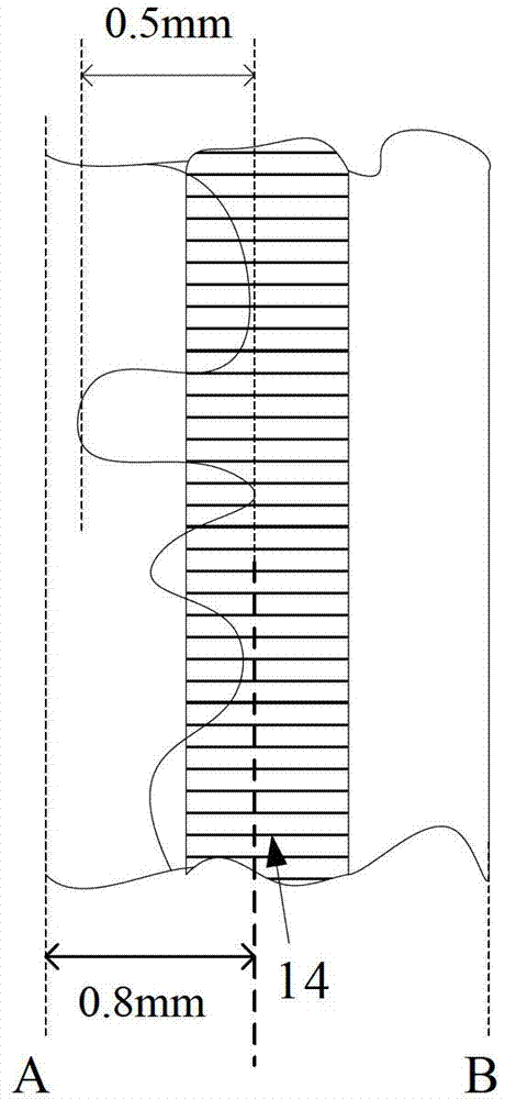
In the prior art, most of the manufacturing methods of the alignment layer are formed by flexographic printing, which can accurately transfer the pattern of the alignment layer required by the display area, but as figure 1 As shown, an irregular shape will be formed at the edge of the alignment layer pattern, and the maximum deviation value is about 0.5mm; in order to avoid that when the alignment layer is made, the edge of the alignment layer extends to the display area, causing display defects, from the display area The distance from the edge A to the edge of the alignment layer should be large enough to negligible the deviation of 0.5mm, half of its design value is set to be greater than 0.8mm, and in order to avoid the alignment layer from overlapping too much on the sealant 14, Affecting the degree of adhesion between the sealant 14 and the substrate, the manufactured sealant 14 will also be far away from the alignment layer, which will make the distance between the edge A of the display area and the edge B of the substrate too large, and the desired Describe the design effect of narrow borders

Method used


Image

  • Substrate containing alignment layer and manufacture method thereof and display device thereof
  • Substrate containing alignment layer and manufacture method thereof and display device thereof
  • Substrate containing alignment layer and manufacture method thereof and display device thereof

Examples


Embodiment Construction

[0029] The following will clearly and completely describe the technical solutions in the embodiments of the present invention with reference to the accompanying drawings in the embodiments of the present invention. Obviously, the described embodiments are only some, not all, embodiments of the present invention.

[0030] An embodiment of the present invention provides a method for manufacturing a substrate including an alignment layer, the method comprising the following steps:

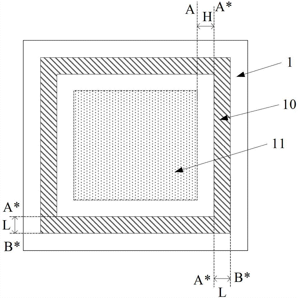
[0031] S1, such as figure 2 As shown, a photosensitive film is fabricated on the substrate 1, and a frame-shaped photosensitive pattern 10 is formed on the periphery of the display area of ​​the substrate through a patterning process; wherein, the inner edge A of the frame-shaped photosensitive pattern 10 * and outer edge B * , are all parallel to the corresponding edge A of the display area 11 .

[0032] Wherein, the material of the photosensitive pattern is a photosensitive resin material. Exemp...


PUM


Abstract

The invention provides a substrate containing an alignment layer, a manufacture method thereof and a display device thereof. The alignment layer with regular and aligned edges can be manufactured on the substrate, and the design effect of a narrow boarder can be achieved. The manufacture method is that a photosensitive thin film is manufactured on the substrate, and a frame-shaped photoreceptive pattern is formed on the periphery of a display area of the substrate through picture composition technique, wherein both the inner edge and the outer edge of the frame-shaped photoreceptive pattern are parallel to corresponding edges of the display area, an alignment layer thin film is manufactured on the substrate where the photoreceptive pattern is formed, the photoreceptive pattern and a part of the alignment layer thin film above the photoreceptive pattern are removed, and therefore the alignment layer is formed.

Description

technical field [0001] The invention relates to the field of liquid crystal display, in particular to a substrate including an alignment layer, a manufacturing method thereof, and a display device. Background technique [0002] A display panel in a liquid crystal display device is composed of two substrates and a liquid crystal layer between them, wherein the liquid crystal layer is obtained by injecting liquid crystal between the two substrates. The liquid crystal display uses electrical signals applied to the display panel to control the rotation of liquid crystals in the liquid crystal layer, thereby realizing image display. In order to obtain uniform brightness and high contrast, it is necessary to arrange the liquid crystal molecules in the display panel along a certain direction initially. Therefore, before the formation of the liquid crystal layer, it is necessary to fabricate alignment layers on the two substrates respectively. [0003] When making the alignment la...

Claims


Application Information

Patent Timeline
Patent Type & Authority Patents(China)
IPC IPC(8): G02F1/1337
Inventor 石领史世明孙韬
Owner BOE TECH GRP CO LTD
Learn More