Micromechanical magnetic field sensor and application thereof
A magnetic field sensor and micromechanical technology, applied in the direction of the size/direction of the magnetic field, piezoelectric/electrostrictive/magnetostrictive devices, instruments, etc., can solve the problem that the output signal cannot eliminate the influence of the capacitive coupling signal, and achieve increased Effects of high intensity, enhanced intensity, and increased sensitivity
- Summary
- Abstract
- Description
- Claims
- Application Information
AI Technical Summary
Problems solved by technology
Method used
Image
Examples
Embodiment 1
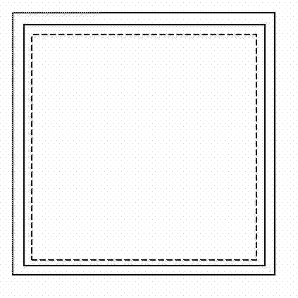
[0087] Such as Figures 2a to 2d As shown, the present invention provides a micromechanical magnetic field sensor, the micromechanical magnetic field sensor at least includes: a pair of resonant oscillators and an insulating layer 6 and a metal coil 7 sequentially formed on the surface thereof, wherein the pair of resonant oscillators includes: The resonant oscillator structure 1 , the main support beam 21 , the first anchor point 41 and the driving electrode 5 . In the first embodiment, the pair of resonant oscillators further includes a first coupling beam 31 and a second anchor point 42 .
[0088] The resonant oscillator structures 1 are two and both are axisymmetric structures, and the symmetry axes of each resonant oscillator structure 1 include at least a first symmetry axis and a second symmetry axis, and the first symmetry axis is perpendicular to the second symmetry axis. axis. The material of the resonator structure 1 is single crystal silicon, polycrystalline sili...
Embodiment 2
[0129] The technical solution of the second embodiment is basically the same as that of the first embodiment, the difference mainly lies in that the structure of the resonant oscillator in the first embodiment is a square plate, and the pair of resonant oscillators includes a first coupling beam, a second anchor point, a second Two coupling beams and the third anchor point; in the second embodiment, the resonant oscillator structure is a rectangular plate, and the resonant oscillator pair does not include the first coupling beam, the second anchor point, the second coupling beam and the third anchor For the rest of the resonant oscillator centering (structure, manufacturing method and working principle), please refer to the relevant description of the first embodiment, and will not repeat them here.
[0130] Such as Figure 3a with 3c As shown, the second embodiment provides a micro-mechanical magnetic field sensor, the micro-mechanical magnetic field sensor at least includes...
Embodiment 3
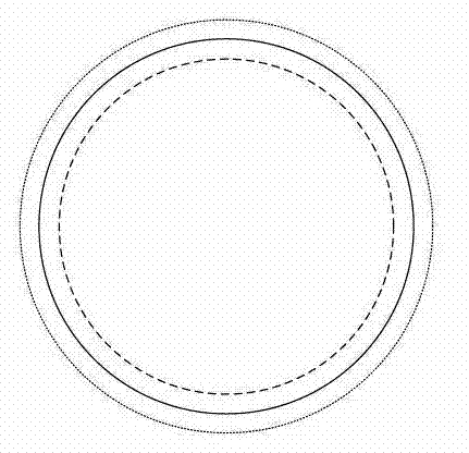
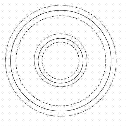
[0144] The technical solution of the third embodiment is basically the same as that of the first embodiment, the main difference is that: the structure of the resonant oscillator in the first embodiment is a square plate; in the third embodiment, the structure of the resonant oscillator is a circular plate, and the resonant oscillator For the rest of the alignment (structure, manufacturing method and working principle), please refer to the relevant description of the first embodiment, and will not repeat them here.
[0145] Such as Figure 4a with 4b As shown, the third embodiment provides a micro-mechanical magnetic field sensor, the micro-mechanical magnetic field sensor at least includes: a pair of resonant oscillators and an insulating layer 6 and a metal coil 7 sequentially formed on the surface thereof, wherein the pair of resonant oscillators It includes: a circular plate resonant oscillator structure 1, a main support beam 21, a first coupling beam 31, a first anchor ...
PUM
 Abstract
Description
Claims
Application Information
 - R&D Engineer
- R&D Manager
- IP Professional
- Industry Leading Data Capabilities
- Powerful AI technology
- Patent DNA Extraction
Browse by: Latest US Patents, China's latest patents, Technical Efficacy Thesaurus, Application Domain, Technology Topic, Popular Technical Reports.
© 2024 PatSnap. All rights reserved.Legal|Privacy policy|Modern Slavery Act Transparency Statement|Sitemap|About US| Contact US: help@patsnap.com


