Power distribution network fault line selection method using zero-sequence current full quantity Hough transformation
A distribution network fault and zero-sequence current technology, which is applied in the direction of fault location, measurement of electrical variables, and measurement of electricity, can solve the problem of poor similarity of zero-sequence current waveforms in sound lines, randomness, and difficulty in reliably capturing the first wave head of a traveling wave and other issues, to achieve the requirements of reducing the hardware sampling rate, improve the ability to resist noise interference, and overcome the effect of perishability
- Summary
- Abstract
- Description
- Claims
- Application Information
AI Technical Summary
Problems solved by technology
Method used
Image
Examples
Embodiment 1
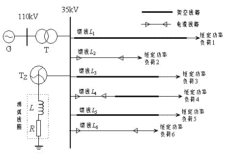
[0071] Such as figure 2 Shown: 110kV / 35kV distribution network single-phase ground fault simulation model, the power supply voltage in the figure is 110kV, which is changed to 35kV by the transformer and then sent to the load end. It has 6 feeders, and the neutral point of the Z-shaped transformer passes through the arc suppression Coil series resistor to ground. overhead feeder L 1 =15km, L 3 =18km, L 5 =30km, wire-cable hybrid feeder L 4 =17km, the overhead feeder is 12km, the cable is 5km, and the cable feeder L 2 =6km, L 6 =8km. Among them, the overhead feeder is JS1 pole type, LGJ-70 type conductor, the span is 80m, and the cable feeder is YJV23-35 / 95 type cable. G in the power grid is an infinite power supply; T is the main transformer with a transformation ratio of 110 kV / 35kV, and the connection group is Y N / d11;T Z Is a zigzag transformer; L is the arc suppression coil; R is the damping resistance of the arc suppression coil. The feeder adopts three ...
Embodiment 2
[0074] Embodiment 2: The single-phase ground fault simulation model of the 110kV / 35kV distribution network is the same as that of Embodiment 1, and the distance from the feeder L 2 A single-phase ground fault occurs at 2 km from the beginning, the ground resistance is 200Ω, the fault angle is 30°, and the sampling frequency is 10kHz. According to the same method as Example 1, the time window data of 1ms after the fault and 0.5ms before the fault are selected to generate a two-dimensional image in JPG format, and the corresponding angles of each feeder are performed after Hough transformation , taking the result of the symbolic function calculation, =(1,-1,1,1,1,1), so the feeder can be judged L 2 for the fault feeder.
PUM
 Abstract
Description
Claims
Application Information
 - R&D
- Intellectual Property
- Life Sciences
- Materials
- Tech Scout
- Unparalleled Data Quality
- Higher Quality Content
- 60% Fewer Hallucinations
Browse by: Latest US Patents, China's latest patents, Technical Efficacy Thesaurus, Application Domain, Technology Topic, Popular Technical Reports.
© 2025 PatSnap. All rights reserved.Legal|Privacy policy|Modern Slavery Act Transparency Statement|Sitemap|About US| Contact US: help@patsnap.com


