
Reverse guiding system and adjustment control method thereof

A technology of guidance system and control method, applied in the direction of closed-circuit television system, vehicle components, optical observation device, etc., which can solve problems such as crash accidents, non-adjustable, safety hazards of reversing cameras, etc., to achieve safety assurance and eliminate non-adjustable effects

Inactive Publication Date: 2015-05-20
广东好帮手丰诺电子科技有限公司
View PDF4 Cites 0 Cited by
  • Summary
  • Abstract
  • Description
  • Claims
  • Application Information

AI Technical Summary

Problems solved by technology

Almost all cameras with reversing scale lines on the market now have inaccurate and non-adjustable scale lines, because the installation angles and heights of cameras of different models are completely inconsistent, and there will be great deviations in imaging. The result is Not only did it fail to provide a distance reference for the car owner, but sometimes it misled the car owner, and some car owners even mistakenly believed that the ruler line was accurate and thus caused a crash
[0004] At present, most of the reversing cameras on the market are installed at the license plate lights, but the license plate lights are not in the center of the rear of the car, so after the camera is installed, there will be a certain deviation between the imaging center and the center of the rear of the car. If you need to ensure the safety warning line at the rear of the car ( Usually defined as 30CM), all the scenes directly behind the car body are visible in the imaging area of ​​the camera, which requires high optical lens requirements for the camera (horizontal angle requirements), and high requirements represent high costs; if installed at the license plate light If the horizontal angle of the optical lens is not enough, there will be a large blind spot in its imaging, making it impossible for the owner to know the existence and specific location of obstacles in the blind spot, so the existing reversing camera has a large safety hazard

Method used


Image

  • Reverse guiding system and adjustment control method thereof
  • Reverse guiding system and adjustment control method thereof
  • Reverse guiding system and adjustment control method thereof

Examples


Embodiment Construction

[0051] In order to make the purpose, technical solution and advantages of the present invention clearer and clearer, the present invention will be further described in detail below with reference to the accompanying drawings and examples. It should be understood that the specific embodiments described here are only used to explain the present invention, not to limit the present invention.

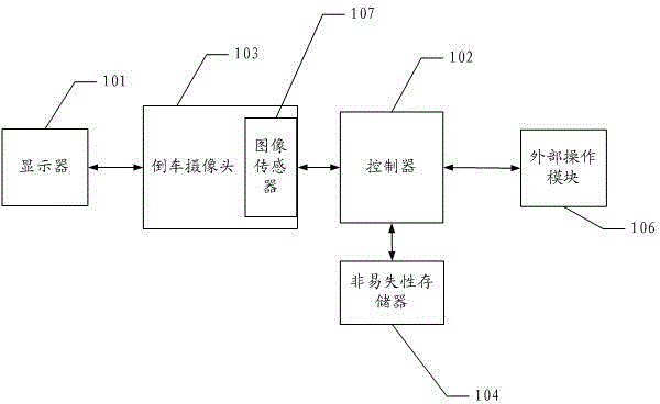
[0052] See figure 1 , figure 1 It is a structural schematic diagram of a preferred embodiment of a reversing guidance system of the present invention.

[0053] Depend on figure 1 It can be seen that the reversing guidance system includes a reversing camera 103 for acquiring a reversing image, and a display 101 for displaying the reversing image; the reversing guidance system also includes: an external operation module 106 for receiving operation data from the owner; A controller that receives the operation data and converts it into an operation command, transmits the operation command to...


PUM


Abstract

The invention discloses a reverse guiding system and an adjustment control method thereof. The reverse guiding system comprises a reverse camera, a displayer, an external operation module, a controller and a nonvolatile memory, wherein the reverse camera is used for obtaining reverse images, the displayer is used for displaying the reserve images, the reverse camera further comprises an image sensor which is used for adjusting the reverse images, the external operation module is used for receiving operation data of a car owner, the controller is used for receiving the operation data, converting the operation data into operation commands, transmitting the operation commands to the image sensor through an image sensor interface and sending the operation commands into the nonvolatile memory for storage, and the nonvolatile memory is used for storing the operation commands; and the reverse guiding system can solve the disadvantage that the existing reverse camera cannot adjust reverse images.

Description

technical field [0001] The invention relates to the field of reversing cameras, in particular to a reversing guidance system and an adjustment control method thereof. Background technique [0002] With the rapid development of social economy, cars have increasingly become an indispensable tool in people's daily work and life. As a safety driving aid tool that can provide visual images for car owners, car cameras are increasingly popular due to their low price and high practicability. [0003] In the prior art, the imaging of a common reversing camera is divided into two parts: the image and the scale line (or scale line). The scale line can provide a reference for the owner to visually measure the distance between the real object and the vehicle, so its accuracy is very important. Almost all cameras with reversing scale lines on the market now have inaccurate and non-adjustable scale lines, because the installation angles and heights of cameras of different models are compl...

Claims


Application Information

Patent Timeline
Patent Type & Authority Patents(China)
IPC IPC(8): B60R1/00B60R11/02B60R11/04H04N7/18
Inventor 敖海均孟海飞戴洪万甘桂亮
Owner 广东好帮手丰诺电子科技有限公司
Learn More