
Synchronous tension adjustment winding machine

A synchronous adjustment and winding machine technology, applied in the field of winding machines, can solve the problems of different tension, poor operability, wire breakage, etc., and achieve the effects of convenient and fast adjustment, strong pressure resistance, and uniform tension

Inactive Publication Date: 2013-02-13
河北瑞兴橡塑有限公司
View PDF4 Cites 4 Cited by
  • Summary
  • Abstract
  • Description
  • Claims
  • Application Information

AI Technical Summary

Problems solved by technology

This type of winding machine has the following defects: first, before production, the operator must adjust the adjusting gasket in front of each bobbin, the adjustment process is cumbersome, the time is long, and the operability is poor; The adjustment gasket is adjusted by the operator's visual inspection and experience, resulting in uneven tension of each wire; third, when the wire capacity of each spool is different, the tension is different, and the difference is very large; fourth, because the side of each spool The friction coefficient of the friction surface and the friction coefficient of each spool in different periods are different, resulting in different tension of the wire
Due to the uneven tension of the skeleton layer wire, when subjected to high-pressure impact, it is easy to cause the wire to break, and during production, the inner rubber layer may be damaged, affecting the service life of the product, and even causing waste

Method used


Image

  • Synchronous tension adjustment winding machine
  • Synchronous tension adjustment winding machine
  • Synchronous tension adjustment winding machine

Examples


Embodiment Construction

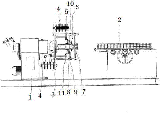
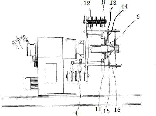
[0021] The structure of the tension synchronous adjustment winding machine proposed by the present invention will be further described below in conjunction with the accompanying drawings.

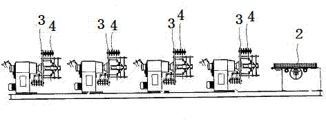
[0022] like figure 1 , figure 2 and Figure 5 Shown is a schematic diagram of the structure of the tension synchronous adjustment winding machine. Its structure includes a frame 1, a traction mechanism 2, a turntable 3, a pay-off mechanism 4, a pay-off direction change mechanism 5, a line distribution disc 6 and a mouth shape 7, and the side of the pay-off direction change mechanism 5 close to the line distribution disc 6 A fixed disk 8 is provided, and a tension adjustment ring 9 is provided on the side of the fixed disk 8 close to the line distribution disk 6. The tension adjustment ring is ring-shaped, and its inner diameter is smaller than the outer diameter of the fixed disk 8. Between the tension adjustment ring 9 and the fixed disk 8 They are connected by a position adjustment me...


PUM


Abstract

The invention belongs to the technical field of winding machines and discloses a synchronous tension adjustment winding machine. The synchronous tension adjustment winding machine is mainly technically characterized by comprising a frame, a traction mechanism, a turntable, a pay-off mechanism, a pay-off reversing mechanism, a wire distribution disc and a mouth, wherein a fixing disc is arranged on one side of the pay-off reversing mechanism close to the wire distribution disc; a tension adjusting ring is arranged on one side of the fixing disc close to the wire distribution disc; an inner diameter of the tension adjusting ring is smaller than an outer diameter of the fixing disc; the tension adjusting ring is connected with the fixing disc through a position adjusting mechanism; a framework layer wire reaches the outer side of the fixing disc through the pay-off mechanism and the pay-off reversing mechanism and enters the wire distribution disc and the mouth through the inner side of the tension adjusting ring; the wire is bent in a certain angle between the fixing disc and the tension adjusting ring; and the bending angle of the wire is adjusted by adjusting the distance between the fixing disc and the tension adjusting ring. Therefore, the adjustment is convenient and rapid, each framework layer wire has uniform tension, and the produced steel tube has high quality and high pressure resistance.

Description

technical field [0001] The invention belongs to the technical field of winding machines, and in particular relates to a tension synchronously adjusting winding machine. Background technique [0002] Spiral rubber hose is a high-pressure liquid delivery pipeline. Because it bears high pressure and is used in a harsh environment, whether the wire tension of the skeleton layer is uniform or not directly affects the pressure bearing capacity and service life of the rubber hose. The more uniform the tension of the skeleton layer wire during the winding process, the stronger the overall pressure bearing capacity of the rubber hose. At present, the spool of the winding machine used to produce rubber hose is installed on the spool rod, and the top spring is installed behind the spool rod, and the top of the spool rod is provided with an adjusting gasket, and the adjustment of each top spring is adjusted by changing the thickness or quantity of the adjusting gasket. The elastic forc...

Claims


Application Information

Patent Timeline
IPC IPC(8): B21F3/04B21F23/00
Inventor 王云霄王云尧
Owner 河北瑞兴橡塑有限公司
Learn More