Double-layer parallel flow evaporator

A parallel flow, evaporator technology, used in evaporators/condensers, refrigeration components, refrigerators, etc., can solve the problems of reduced refrigeration capacity, unfavorable refrigeration oil circulation, and large refrigerant flow resistance.

Inactive Publication Date: 2013-02-06
SHANDONG TONGCHUANG AUTO COOLING SYST
View PDF5 Cites 5 Cited by
  • Summary
  • Abstract
  • Description
  • Claims
  • Application Information

AI Technical Summary

Problems solved by technology

[0002] The utility model patent application with the patent number of 200620033503.X discloses a double-layer thin multi-stage parallel flow evaporator for automobile air conditioners. The main improvement is to change the original stacked evaporator into a double parallel flow structure. The flow resistance of the refrigerant is large, and the left and right arrangement of the liquid collection pipe is not conducive to the circulation of the refrigeration oil, which reduces the cooling capacity

Method used


Image

  • Double-layer parallel flow evaporator
  • Double-layer parallel flow evaporator

Examples


Embodiment Construction

[0015] The present invention is described in detail below in conjunction with accompanying drawing:

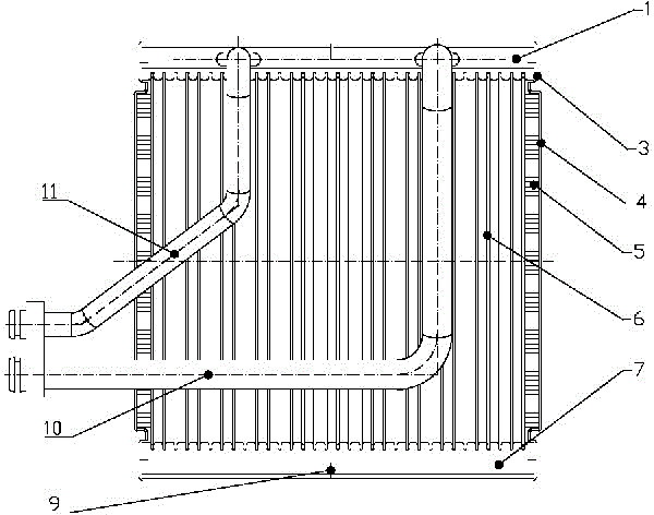
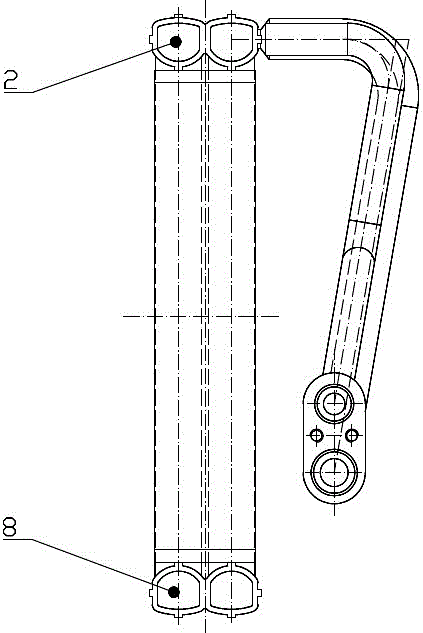
[0016] The double-layer parallel flow evaporator includes two groups of cooling cores arranged one above the other next to each other. The upper cooling core consists of the first liquid collecting pipe 1, the second liquid collecting pipe 7, and The plurality of flat pipes 6 between the second liquid collection pipe 7 are formed, and the lower cooling core is composed of the third liquid collection pipe 2, the fourth liquid collection pipe 8, and the connection between the third liquid collection pipe 2 and the fourth collection pipe. A plurality of flat pipes 6 between the liquid pipes 8 constitute. The first liquid collection pipe 1 is arranged adjacent to the third liquid collection pipe 2, the second liquid collection pipe 7 is arranged adjacent to the fourth liquid collection pipe 8, the first liquid collection pipe 1, the second liquid collection pipe 7, and the second ...


PUM


Abstract

The invention discloses a double-layer parallel flow evaporator which comprises two groups of cooling core bodies which are vertically arranged adjacent to each other, wherein the upper-layer cooling core body consists of a first collector tube, a second collector tube, and a plurality of flat tubes connected between the first collector tube and the second collector tube; the lower-layer cooling core body consists of a third collector tube, a fourth collector tube, and a plurality of flat tubes connected between the third collector tube and the fourth collector tube; separation plates are arranged among the first collector tube, the second collector tube, the third collector tube and the fourth collector tube; the left part of the first collector tube is connected with a liquid inlet tube, and the right part of the first collector tube is connected with a gas outlet tube; and the corresponding parts of the left and right parts of the second collector tube and the fourth collector tube are communicated with each other. According to the double-layer parallel flow evaporator, a refrigerant flows horizontally and is uniform in flow velocity; and according to the collector tubes which are vertically arranged, the cycle efficiency of compressor refrigeration oil is improved, the maintenance rate of an air-conditioning system is reduced, the utilization rate of the radiating area is improved, and the problem that the evaporator is frosted and wetted is effectively improved.

Description

technical field [0001] The invention relates to an evaporator for an automobile air-conditioning system, in particular to a parallel flow evaporator. Background technique [0002] The utility model patent application with the patent number of 200620033503.X discloses a double-layer thin multi-stage parallel flow evaporator for automobile air conditioners. The main improvement is to change the original stacked evaporator into a double parallel flow structure. The flow resistance of the refrigerant is large, and the left and right arrangement of the liquid collection pipe is not conducive to the circulation of the refrigeration oil, which reduces the cooling capacity. Contents of the invention [0003] The object of the present invention is to provide a double-layer parallel-flow evaporator, which has a novel structure and effectively improves the utilization rate of the heat dissipation area. [0004] In order to achieve the above object, the present invention adopts the t...

Claims


Application Information

Patent Timeline
IPC IPC(8): F25B39/02
Inventor 宋洪磊李磊张重先白树兴
Owner SHANDONG TONGCHUANG AUTO COOLING SYST
Why Eureka
Try Eureka