
Hybrid power and electric system of electric car

A technology for electric power systems and electric vehicles, applied in the field of vehicles, can solve problems such as the rapid decline of power output, and achieve the effects of increased endurance, high convenience, low pollution and low impact on the environment

Inactive Publication Date: 2013-02-06
粘育珲
View PDF18 Cites 7 Cited by
  • Summary
  • Abstract
  • Description
  • Claims
  • Application Information

AI Technical Summary

Problems solved by technology

[0009] The invention provides a composite power and power system for electric vehicles, which can solve the problem of rapid decline in power output of traditional pneumatic engines

Method used


Image

  • Hybrid power and electric system of electric car
  • Hybrid power and electric system of electric car
  • Hybrid power and electric system of electric car

Examples


no. 1 example

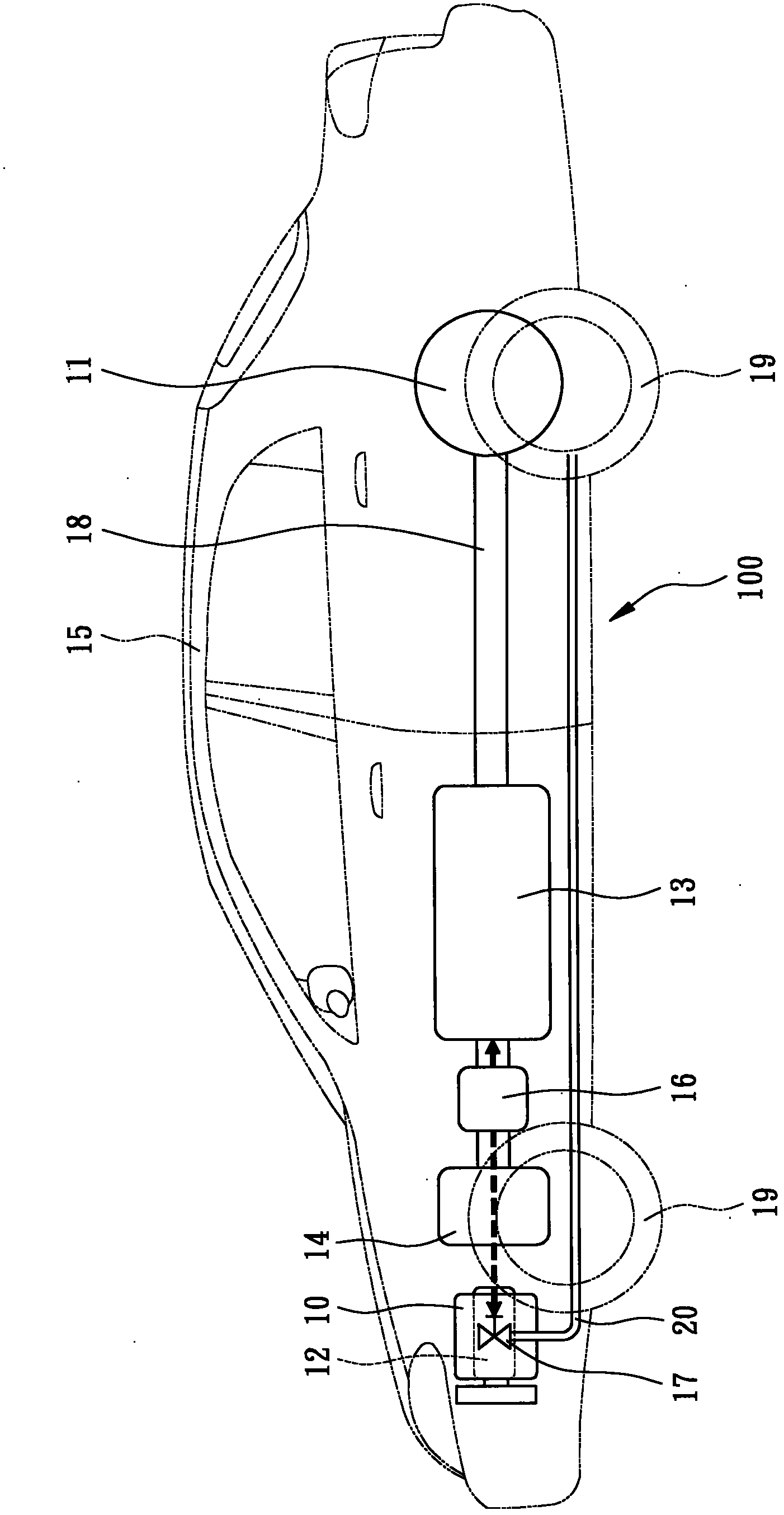
[0041] refer to Figure 1 ~ Figure 3 Shown is a hybrid power system 100 of an electric vehicle provided by a preferred embodiment of the present invention, which includes a pneumatic engine 10, a gas storage device 11, a generator 12, two batteries 13 and a motor 14. constitute. The electric vehicle 15 is powered by the motor 14 , and the power is transmitted to the four wheels 19 by the transmission shaft 18 . The electric vehicle 15 of the present embodiment is an automobile, and of course it can also be applied to motorcycles, electric bicycles, and electric tricycles.

[0042] In one embodiment of the present invention, the pneumatic engine 10 is a device that can receive high-pressure gas to generate power. The pneumatic engine 10 adopts U.S. Patent No. 7,866,251B2 (corresponding patent: Taiwan, China No. TWI327621, China CN665571, PCT / CN2007 / 001994) power plant technology, and the gas storage device 11 provides compressed high-pressure gas, in one embodiment of the pre...

no. 2 example

[0072] Figure 4 , Figure 5 It is a front view and a top view of a motorcycle using the hybrid power and electric system of the electric vehicle of the present invention. It includes a pneumatic engine 10 , a gas storage device 11 , a generator 12 , a storage battery 13 , a motor 14 and an energy management module 16 , and the motor 14 provides power for an electric vehicle 15 . In addition to being used in motorcycles, the hybrid power and electric system of the electric vehicle in this embodiment are the same as those in the first embodiment, and will not be repeated here.

[0073] Of course, the hybrid power and power system of the electric vehicle of the present invention can also be used in combination with traditional fossil fuel engine vehicles, and the energy management module 16 can be used for intelligent control, which can increase the vehicle endurance of traditional fossil fuel engines and reduce fuel consumption and carbon dioxide emissions. emission.


PUM


Abstract

The invention provides a hybrid power and electric system of an electric car, provides two electric sources for electric cars and solves the problems that an electric car is insufficient in endurance and is impractical due to long charging time. The hybrid power and electric system of the electric car comprises a pneumatic engine, a gas storage device, a generator, a storage battery and a motor. The pneumatic engine can receive compressed gas to generate electricity. The gas storage device provides compressed gas for the pneumatic engine. The generator is driven by the pneumatic engine to generate electricity. The storage battery can be charged by external electricity or electricity of the generator. The motor provides a power source for the electric car, and the generator is driven by the storage battery or the pneumatic engine to generate electricity to power the motor. Therefore, the electric car can be charged while being driven, endurance is increased, high-pressure gas is easy to use to inflate fast and easy to obtain, price is low, and pollution is avoided.

Description

technical field [0001] The invention relates to a vehicle, especially a compound power and power system of an electric vehicle. In addition to the power provided by the battery, it especially uses a pneumatic engine to drive a generator to generate electricity, and at the same time can provide power to the motor to drive the car, and can also provide power Charge the battery. Background technique [0002] Fossil fuels are currently the main source of power for vehicles, relying on the combustion of fossil fuels to supply the engine to output power to drive vehicles. In addition to environmental pollution, the combustion of fossil fuels is also the culprit of global warming. Therefore, various alternatives The plan was born accordingly. [0003] The main appeal of electric vehicles is to solve the above-mentioned fossil fuel pollution and the impact on global warming. However, electric vehicles rely on batteries for power supply. The biggest problem with batteries is the ins...

Claims


Application Information

Patent Timeline
IPC IPC(8): B60K6/00B60K3/00B60L11/18
CPCY02T10/7005Y02T10/70
Inventor 粘育珲高国宝
Owner 粘育珲
Learn More