Roller adjusting mechanism of small standard copper belt rolling machine

A technology of roll adjustment and small size, applied in the direction of metal rolling mill stand, metal rolling stand, metal rolling, etc. Low technical personnel requirements, compact structure and high production efficiency

Active Publication Date: 2015-02-25
THE NORTHWEST MACHINE
View PDF6 Cites 0 Cited by
  • Summary
  • Abstract
  • Description
  • Claims
  • Application Information

AI Technical Summary

Problems solved by technology

This structure has the following disadvantages for the adjustment of small-sized copper strip (width ≤ 3mm) rolling mill rolls: 1. It is difficult to ensure that the adjustments at both ends are the same for individual adjustments, and there are always errors, that is, it is difficult to adjust to the parallel between the upper roll and the lower roll. Or it has been adjusted parallel, and it has to be readjusted when the specification is changed; 2. Manual adjustment is entirely based on hand feeling, which requires a high level of operator proficiency, and generally requires professional training before it can be operated; 3. The products produced Low quality, only suitable for low-end customers; 4. Complicated operation and low production efficiency

Method used


Image

  • Roller adjusting mechanism of small standard copper belt rolling machine
  • Roller adjusting mechanism of small standard copper belt rolling machine
  • Roller adjusting mechanism of small standard copper belt rolling machine

Examples


Embodiment Construction

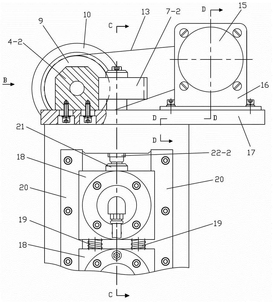
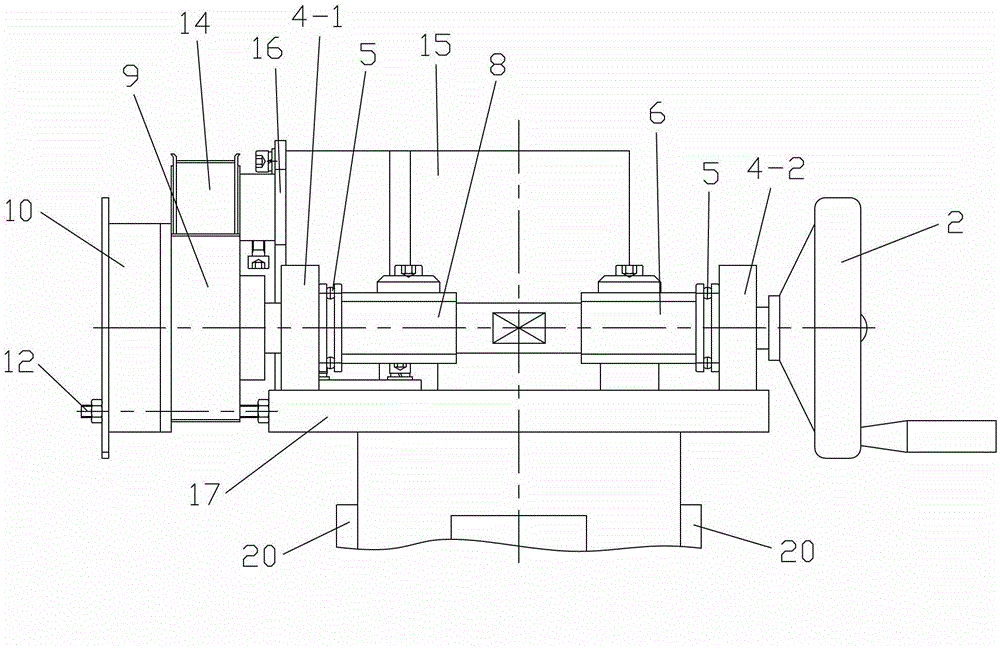
[0032] Such as Figure 1 to Figure 5 As shown, the present invention includes mounting plate 17, worm screw 8, worm screw cover 6, hand wheel 2, nut 1, helical gear one 7-1, helical gear two 7-2, timing pulley one 9, timing belt 13, timing belt Wheel two 14, reduction motor 15 and electromagnetic clutch 10, described installation plate 17 is fixed on the frame 26 that is used to support and install roll 23 to be adjusted, and described worm screw 8 passes through support plate one 4-1 that is sleeved on the worm screw 8 and the support plate two 4-2 are supported and installed on the mounting plate 17, the inner sides of the support plate one 4-1 and the support plate two 4-2 are all provided with thrust bearings 5, and the mounting plate 17 is provided with thrust bearings for pushing the Adjust the slide block 18 on the two ends of the roll 23 along the screw shaft one 22-1 and the screw shaft two 22-2 that slide up and down along the guide bar 20 installed on the frame 26, ...


PUM


Abstract

The invention discloses a roller adjusting mechanism of a small standard copper belt rolling machine, comprising an installation plate, a worm, a worm sleeve, a hand wheel, a nut, bevel gears I and II, synchronous pulleys I and II, a reduction motor and an electromagnetic clutch, wherein the installation plate is fixed on a rack provided with a roller to be adjusted in a support mode, the worm is arranged on the installation plate provided with screw shafts I and II, the bevel gear I is fixed on the screw shaft I and is meshed with the worm, the bevel gear II is fixed on the screw shaft II, the worm sleeve is sheathed at the worm and is meshed with the bevel gear II, the hand wheel is fixed at the outer end of the worm sleeve, the nut is arranged at one end of the worm, the synchronous pulley I is sheathed at the other end of the worm, the electromagnetic clutch is positioned at the outer end surface of the synchronous pulley I, the synchronous pulley II is arranged at the reduction motor, and the synchronous pulleys I and II are connected by a synchronous belt. According to the roller adjusting mechanism of the small standard copper belt rolling machine, adjustment on the small standard copper belt rolling machine is realized, the adjusting is simple, the labor intensity is low and the production efficiency is high.

Description

technical field [0001] The invention belongs to the technical field of metallurgical equipment, and in particular relates to a small-sized copper strip rolling mill for rolling round copper wires, in particular to a roll adjustment mechanism of the small-sized copper strip rolling mill. Background technique [0002] The rolls of existing copper strip mills are purely manually adjusted, and a set of independent hand wheel adjustment mechanisms are respectively arranged at both ends of the rolls. This structure has the following disadvantages for the adjustment of the small-sized copper strip (width ≤ 3mm) rolling mill rolls: 1. It is difficult to ensure that the adjustment amount at both ends is the same for individual adjustment, and there is always an error, that is, it is difficult to adjust the upper roll to be parallel to the lower roll. Or it has been adjusted parallel, and it has to be readjusted when the specification is changed; 2. Manual adjustment is entirely based...

Claims


Application Information

Patent Timeline
Patent Type & Authority Patents(China)
IPC IPC(8): B21B31/16
Inventor 赵艳丽
Owner THE NORTHWEST MACHINE
Why Eureka
Try Eureka