Method and device for detecting optical fiber ring quality based on optical coherence tomography

A technology of optical coherence tomography and scanning technology, which is applied in the field of optical fiber wrapping and detection, can solve the problems of unable to find the optical fiber loop, long winding cycle, difficult to ensure quality, etc. Effect

Active Publication Date: 2014-12-03
苏州光环科技有限公司
View PDF4 Cites 0 Cited by
  • Summary
  • Abstract
  • Description
  • Claims
  • Application Information

AI Technical Summary

Problems solved by technology

The winding process of the four-stage symmetrical optical fiber ring is complicated, the winding cycle is long, and the quality of manual winding is not easy to guarantee, because it needs to change layers many times, and some defects are prone to occur when winding the optical fiber ring
Therefore, at present, all optical fiber ring manufacturers do not have such a detection link. If the quality of the optical fiber ring is found to be poor, at most they can only be disassembled and rewound. , and it is impossible to judge what causes the quality problem, so it is very likely that the reason for the poor quality of the fiber ring cannot be found after the fiber ring is disassembled, and it is impossible to guide the improvement of the winding process and the quality level of the fiber ring

Method used


Image

  • Method and device for detecting optical fiber ring quality based on optical coherence tomography
  • Method and device for detecting optical fiber ring quality based on optical coherence tomography
  • Method and device for detecting optical fiber ring quality based on optical coherence tomography

Examples


Embodiment Construction

[0041] A method and device for detecting the quality of an optical fiber ring based on optical coherence tomography technology proposed by the present invention are described in detail in conjunction with the accompanying drawings and embodiments as follows:

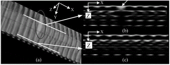
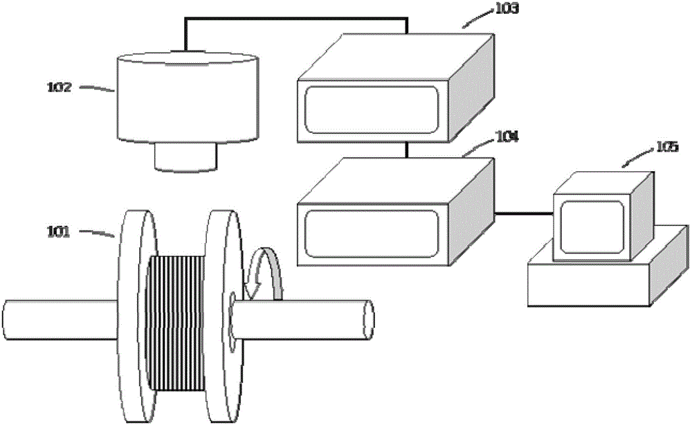
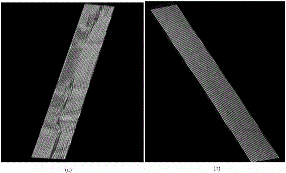
[0042] The device used in a method embodiment of the present invention is as figure 1 As shown, the device includes: a rotating mechanism for installing the fiber ring under test (not shown in the figure); an optical coherence tomography system, the probe of which is placed on the fiber ring under test for scanning the fiber ring, And collect the OCT information of the optical fiber ring; a computer is connected to the optical coherence tomography system to process the OCT information of the measured optical fiber ring and perform three-dimensional imaging on it. The image of the glue on the ring to judge the quality of the fiber ring.

[0043] The optical coherence tomography imaging system of the device in this embodi...


PUM


Abstract

The invention relates to a method and device for detecting an optical fiber ring quality based on optical coherence tomography, belonging to the technical fields of optical measurement, optical fiber sensing and optical fiber detecting. The method comprises the following steps: a to-be-detected optical fiber ring is fixed on a rotating mechanism; an optical coherence tomography system probe is vertically fixed above the to-be-detected optical fiber ring; the optical fiber ring is rotated by taking the center of circle of the optical fiber ring as a rotary axis; one-dimensional scanning on the to-be-detected optical fiber ring along the axial direction of the to-be-detected optical fiber ring is executed by a scanning probe of the optical coherence tomography system to obtain the OCT (optical coherence tomography) information of the to-be-detected optical fiber ring; a three-dimensional image is rebuilt according to the OCT information; whether defects exist on and below the surface of the to-be-detected optical fiber ring is judged through the rebuilt image; and the positions of the defects are determined according to the uneven positions of the image to eliminate defects. According to the method, the quality of finished products of the optical fiber rings and winding defects generated in the winding process of the optical fiber rings are detected by utilizing the OCT; and precisions of various angle sensors using optical fiber rings can be effectively improved.

Description

technical field [0001] The invention belongs to the technical field of optical measurement, optical fiber sensing and detection, and relates to optical coherence tomography (Optical Coherence Tomography, OCT for short) technology, optical fiber surround system and detection technology and method. Background technique [0002] The fiber optic ring is the core of the fiber optic gyroscope. For the fiber optic gyroscope, the fiber optic ring is not only the way to improve the accuracy, but also the main factor affecting the accuracy. How to wind a high-quality fiber optic ring is very important to the fiber optic gyroscope. In the winding process of the optical fiber ring, special winding methods, precise winding technology, perfect packaging process, and appropriate selection of optical fiber ring glue are required to ensure that the optical fiber ring has high-quality static characteristics (low polarization crosstalk, low insertion loss, etc.) and high-quality transient cha...

Claims


Application Information

Patent Timeline
Patent Type & Authority Patents(China)
IPC IPC(8): G01M11/00
Inventor 姚晓天李志宏孟卓
Owner 苏州光环科技有限公司
Why Eureka
Try Eureka