Potential energy power generation device for vehicular transmission shafts

A technology for power generation devices and transmission shafts, which is applied in the direction of electromechanical devices, engines, electrical components, etc., can solve problems such as poor utilization, achieve huge social, economic and environmental protection benefits, save fuel, and be easier to manufacture and install.

Inactive Publication Date: 2013-01-30
陈冠卿
View PDF8 Cites 2 Cited by
  • Summary
  • Abstract
  • Description
  • Claims
  • Application Information

AI Technical Summary

Problems solved by technology

As it stands, this potential energy is ...

Method used


Image

  • Potential energy power generation device for vehicular transmission shafts

Examples


Embodiment Construction

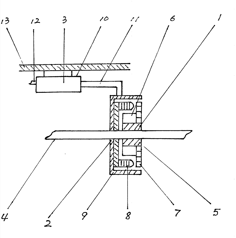
[0011] exist figure 1 Among them, 1 is the transmission shaft rotor, 2 is the retractable movable stator, and 3 is the stator clutch. The transmission shaft rotor 1 is composed of a transmission shaft 4 , a rotor holder 5 , a rotor 6 and a fan 7 . Transmission shaft 4 is the power transmission shaft of the vehicle. The rotor fixing frame 5 is made of metal or plastic, and is fixedly installed on the transmission shaft 4 . The rotor fixing frame 5 can install, fix and protect the rotor 6 . The rotor 6 is made of neodymium-iron-boron permanent magnet material, and has multiple pieces, which are inlaid and fixed on the rotor fixing frame 5 . Fan 7 is installed on the rotor fixed frame 5, and its effect is that the present invention carries out pneumatic cooling to its inside when working, unlikely to be damaged because of excessive temperature. The telescopic movable stator 2 is composed of a stator 8 and an end cover 9 . The stator 8 is composed of a stator core and a stato...


PUM


Abstract

The invention belongs to the field of vehicular power generation equipment, and relates to a potential energy power generation device for vehicular transmission shafts, wherein the device can be applied to automobiles, electric vehicles, hybrid vehicles, hydrogen-powered vehicles and some wheeled military vehicles. The potential energy power generation device mainly comprises a transmission shaft rotor, a telescopic movable stator and a stator clutch, and by the aid of a control system on a vehicle, a clutch shaft lever is capable of telescoping in a clutch cylinder block to drive the telescopic movable stator and the transmission shaft rotor to be separated and combined. When the telescopic movable stator and the transmission shaft rotor are separated, the speed and bearing capacity of the vehicle are unaffected by the potential energy power generation device; and when the telescopic movable stator and the transmission shaft rotor are combined, a power generation device which uses potential energy and latent energy of the vehicle to generate electric energy can be formed to generate power for vehicular electrical appliances and for driving the vehicle to move. The potential energy power generation device has the advantages of fuel saving, energy conservation, emission reduction, environment friendliness and enormous social, economic and environment protection benefits.

Description

Technical field [0001] The invention belongs to the field of vehicle power generation equipment. Background technique [0002] When the vehicle is driving on the road, due to the continuous change of the topography, the road will have ups and downs. When the vehicle is driving on a downhill road, due to the mass, speed, friction between the wheels and the ground, and the gravitational force of the earth, a very powerful dive force that automatically drives forward and downward will be generated, which is potential energy. In addition, the vehicle will produce strong inertial motion when driving on a flat road, especially at high speed. This potential energy is actually an endless source of energy. As it stands, this potential energy is not well and efficiently utilized in vehicles. Contents of the invention [0003] The purpose of the present invention is to overcome the deficiencies of the prior art, and to provide a vehicle drive shaft potential energy generating devi...

Claims


Application Information

Patent Timeline
IPC IPC(8): F03G3/00H02K7/10
Inventor 陈冠卿陈洪涛陈洪波
Owner 陈冠卿
Why Eureka
Try Eureka