
Self-adaptation optical system near-field wave-front sensor calibration device and calibration method based on phase-diversity method

A wavefront sensor and adaptive optics technology, applied in measurement devices, scientific instruments, measurement optics, etc., can solve problems such as instability, many factors affecting the wavefront control effect, and complex processes, achieving obvious advantages and improving wavefront performance. The effect of front control

Inactive Publication Date: 2013-01-23
INST OF OPTICS & ELECTRONICS - CHINESE ACAD OF SCI
View PDF4 Cites 25 Cited by
  • Summary
  • Abstract
  • Description
  • Claims
  • Application Information

AI Technical Summary

Problems solved by technology

This method has no objective measurement data as a benchmark, and often requires many times of tentative corrections to obtain better results. For some more complex imaging systems, there are many factors affecting the wavefront control effect, and the process is more complicated. instability
In addition, due to the nonlinear response of the corrector, this method of pre-adding the correction amount often cannot achieve a good wavefront control effect

Method used


Image

  • Self-adaptation optical system near-field wave-front sensor calibration device and calibration method based on phase-diversity method
  • Self-adaptation optical system near-field wave-front sensor calibration device and calibration method based on phase-diversity method
  • Self-adaptation optical system near-field wave-front sensor calibration device and calibration method based on phase-diversity method

Examples


Embodiment Construction

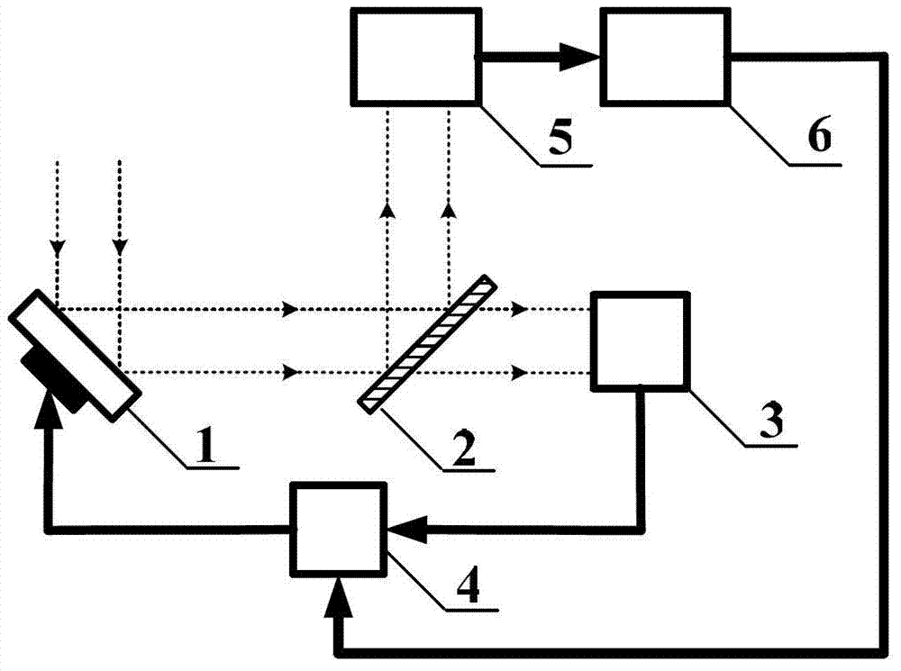
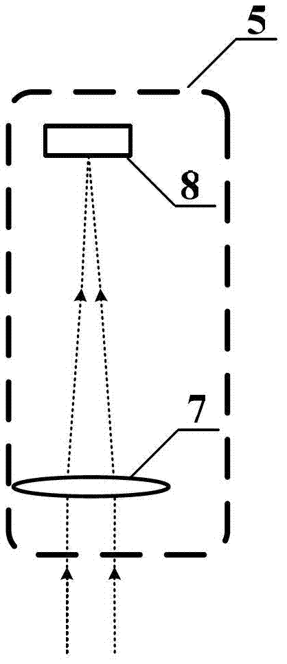
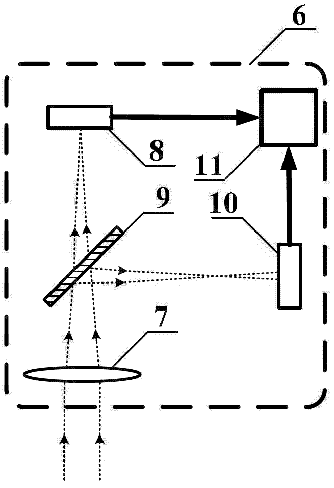
[0025] Such as figure 1 , 2 , 3, the present invention based on phase difference method adaptive optics system near-field wavefront sensor calibration device includes the following parts: wavefront corrector 1, the first beam splitter 2, near-field wavefront sensor 3, wavefront A controller 4, an imaging system 5 and a phase difference wavefront sensor 6. Wherein, imaging system 5 is made up of two parts of imaging device 7 and first imaging detector 8; And computer 11 forms.

[0026] Such as figure 2 As shown, the imaging system 5 is usually composed of an imaging device 7 and a first imaging detector 8 located at the focal plane of the system. The light intensity distribution information detected by the first imaging detector 8 includes a near-field wavefront sensor 3 It is impossible to directly detect the non-common optical path part in the static aberration of the full optical path of the adaptive optics system. For a traditional adaptive optics system based on a ne...


PUM


Abstract

The invention discloses a self-adaptation optical system near-field wave-front sensor calibration device and a calibration method based on a phase-diversity method. The self-adaptation optical system near-field wave-front sensor calibration device consists of a wave-front corrector, a spectroscope, a near-field wave-front sensor, a wave-front controller, an imaging system and a phase-diversity wave-front sensor. According to the method, the phase-diversity wave-front sensor is used for measuring the static aberration of the whole system, and the wave-front controller is used for controlling the wave-front corrector to correct the static aberration; and after the static aberration is corrected, the zero point at the reference position of the near-field wave-front sensor at the pupil plane position is calibrated or the zero point of the absolute aberration is set, and the two zero points are used as the wave-front control objective of the self-adaptation optical system to effectively correct the static aberration of the whole optical path. According to the self-adaptation optical system near-field wave-front sensor calibration device and the calibration method, the static aberration of the whole optical path can be effectively corrected, the wave-front control error caused by the non-linear response of the corrector can be avoided, and the correction capability of the self-adaptation optical system can be improved obviously without obviously increasing the system complexity and the additional aberration.

Description

technical field [0001] The invention relates to a calibration device and a calibration method for a near-field wavefront sensor of an adaptive optical system based on a phase difference method. Background technique [0002] Adaptive optics system is an effective means to improve the imaging resolution of most optical systems at present, especially for large optical systems with high complexity and many optical components. The adaptive optics system mainly includes three parts: wavefront detector, wavefront controller and wavefront corrector. First, the wavefront detector detects the wavefront distortion in the optical path, and calculates the correction amount of the corresponding wavefront corrector through the wavefront controller, and finally implements the wavefront correction through the wavefront corrector, so as to achieve higher imaging quality Or energy concentration, etc. Due to the nonlinear response characteristics of the wavefront corrector, the current main a...

Claims


Application Information

Patent Timeline
IPC IPC(8): G01J9/00G01M11/02
Inventor 饶长辉罗群顾乃庭鲍华
Owner INST OF OPTICS & ELECTRONICS - CHINESE ACAD OF SCI
Learn More