
Slide valve type hydraulic valve with differential motion function

A technology of hydraulic valves and functions, which is applied in the direction of fluid pressure actuators, servo motor components, mechanical equipment, etc., and can solve problems such as complex valve body structure, increased product cost and product failure rate, and inability to realize stepless flow control. Achieve the effect of reducing product cost, less overall structural changes, and easy realization

Active Publication Date: 2015-05-13
SANY HEAVY IND CO LTD (CN)
View PDF8 Cites 0 Cited by
  • Summary
  • Abstract
  • Description
  • Claims
  • Application Information

AI Technical Summary

Problems solved by technology

[0005] 2. In order to realize the differential function, the control valve needs to increase the control oil circuit and installation cavity accordingly, and the structure of the valve body is relatively complicated, which increases the product cost and product failure rate accordingly;
[0006] 3. This kind of control valve can only realize the on-off of the oil circuit, and cannot realize the stepless control of the flow rate

Method used


Image

  • Slide valve type hydraulic valve with differential motion function
  • Slide valve type hydraulic valve with differential motion function
  • Slide valve type hydraulic valve with differential motion function

Examples


Embodiment Construction

[0031] It should be noted that, in the case of no conflict, the embodiments of the present invention and the features in the embodiments can be combined with each other. The present invention will be described in detail below with reference to the accompanying drawings and examples.

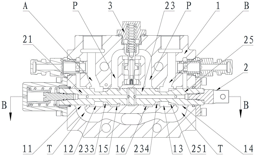
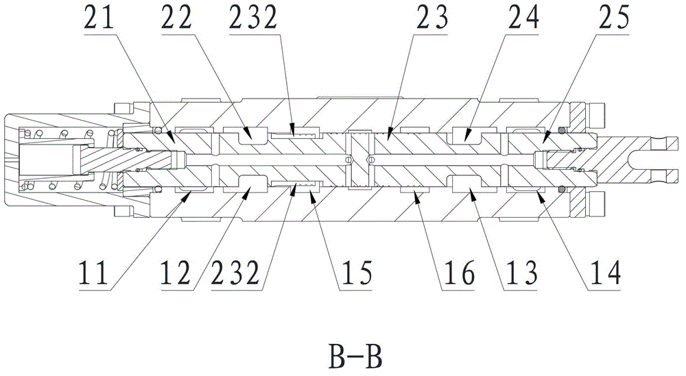
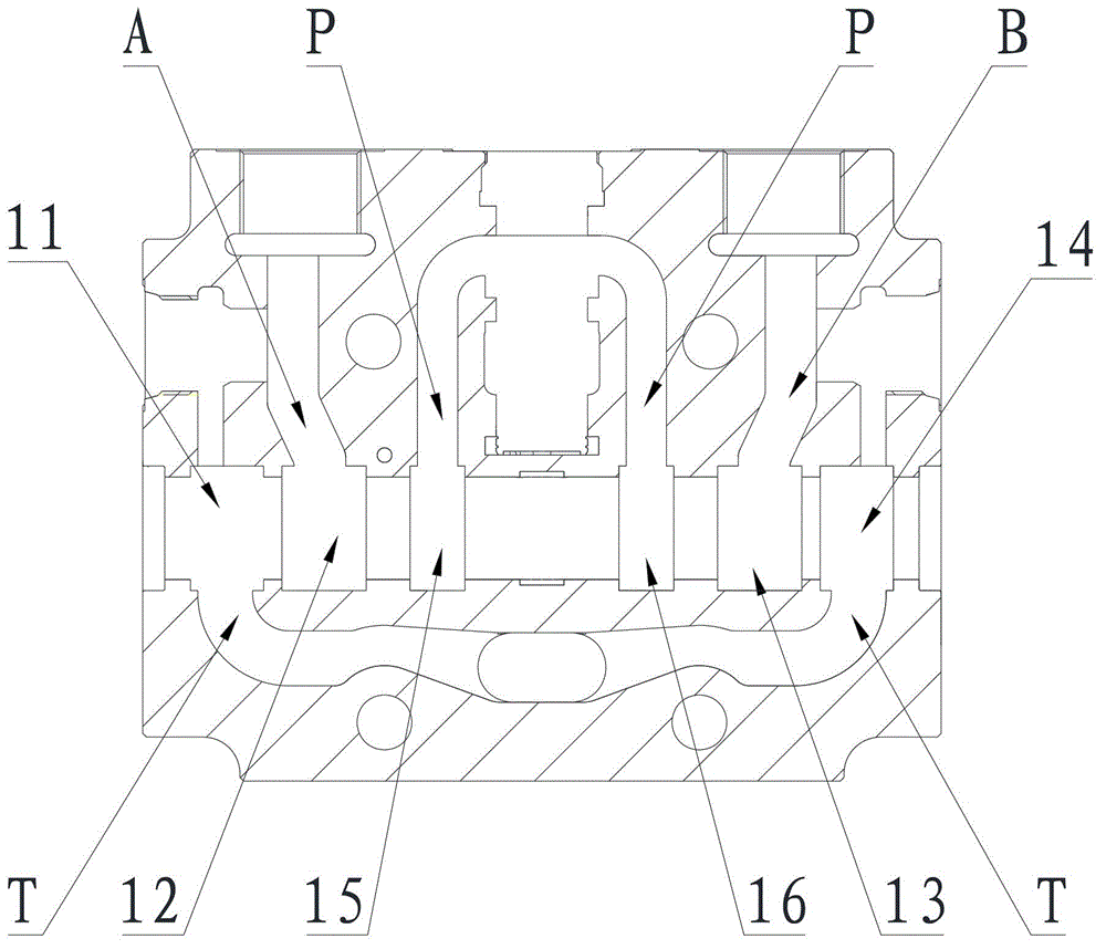
[0032] Figure 1 to Figure 5 That is the relevant drawings of this embodiment, as shown in the figure, the slide valve hydraulic valve with differential function described in this embodiment includes a valve body 1 and a valve core 2 arranged in the hole of the valve body 1, The first undercut groove 11, the second undercut groove 12, the fifth undercut groove 15, the sixth undercut groove 16, the third undercut groove 13 and the fourth undercut groove are sequentially arranged in the hole of the valve body 1. 14, the first undercut groove 11 and the fourth undercut groove 14 communicate with the oil return port T, the second undercut groove 12 and the third undercut groove 13 communicate with t...


PUM


Abstract

The invention provides a slide value type hydraulic valve with a differential motion function. The slide value type hydraulic valve comprises a valve body and a valve element which is arranged in a valve body hole; a first undercutting groove, a second undercutting groove, an oil inlet undercutting groove, a third undercutting groove and a fourth undercutting groove are arranged in the valve body hole in sequence, wherein the first undercutting groove and the fourth undercutting groove are communicated with an oil return opening, the second undercutting groove and the third undercutting groove are communicated with a working oil port respectively, and an oil inlet undercutting groove is communicated with an oil inlet; the valve element comprises a left circular bead, a left shaft neck, a middle circular bead, a right shaft neck and a right circular bead from left to right; a circular groove, a first valve port and a second valve port are arranged on the excircle of the left part of the middle circular bead, wherein the first valve port and the second valve port are not communicated with each other; a third valve port and a fourth valve port which are communicated with the right shaft neck are arranged on the excircle of the right part of the middle circular bead and the excircle of the left part of the right circular bead respectively. The slide value type hydraulic valve realizes differential motion function through improving the structure of a main valve element of the hydraulic valve, the integral structure is changed little, so as to reduce the product cost and failure rate of the product; the differential motion function is realized, and stepless control of flow can be realized at the same time.

Description

technical field [0001] The invention relates to the technical field of hydraulic transmission and control, in particular to a slide valve hydraulic valve with a differential function. Background technique [0002] At present, there are mainly the following ways to realize the differential function of the oil cylinder: the differential function in the oil cylinder, the differential function in the control valve, the addition of a superimposed differential valve on the basis of the original control valve, and the hydraulic system through The pipeline is connected and combined with electrical control to realize the differential function. [0003] The above-mentioned ways to realize the differential function have their own disadvantages. For the existing control valves with differential functions, there are mainly the following disadvantages: [0004] 1. In order to realize the differential function, it is necessary to add logic valves, control valves and other components in th...

Claims


Application Information

Patent Timeline
Patent Type & Authority Patents(China)
IPC IPC(8): F15B13/02
Inventor 彭勇刘正雷陆晓兵
Owner SANY HEAVY IND CO LTD (CN)
Learn More