Secondary air injection system and method

A secondary air and exhaust port technology, applied in exhaust devices, mechanical equipment, engine components, etc., can solve problems such as reducing exhaust pressure pulse energy

Inactive Publication Date: 2013-01-23
GM GLOBAL TECH OPERATIONS LLC
View PDF5 Cites 2 Cited by
  • Summary
  • Abstract
  • Description
  • Claims
  • Application Information

AI Technical Summary

Problems solved by technology

However, secondary air injection systems can allow crosstalk or degradation between cylinder banks by allowing communication between cylinder bank exhaust streams, thereby reducing the energy provided by the exhaust pressure pulses

Method used


Image

  • Secondary air injection system and method
  • Secondary air injection system and method

Examples


Embodiment Construction

[0051] The following detailed description is merely exemplary in nature and is not intended to limit the disclosure, its application, or uses. It should be understood that throughout the drawings, corresponding reference numerals indicate like or corresponding parts and features.

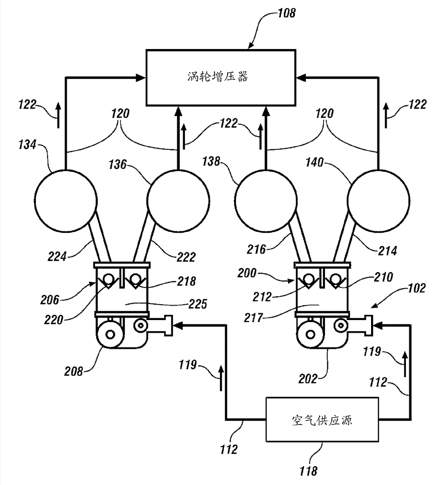
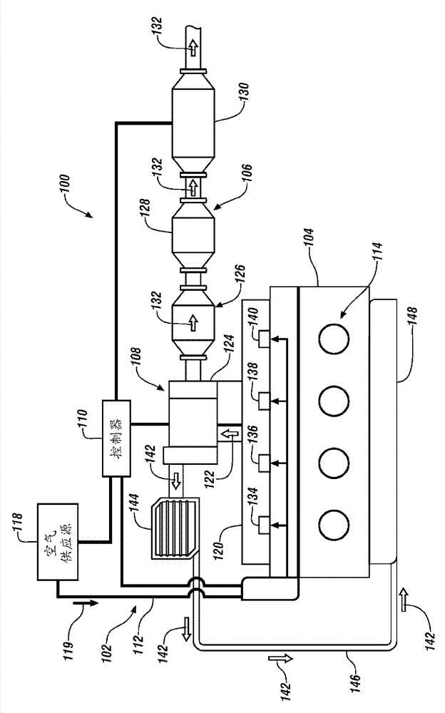
[0052]According to an exemplary embodiment of the present invention, FIG. 1 illustrates an exemplary internal combustion engine 100, in this case an inline four cylinder engine, including a secondary air injection system 102, an engine block and cylinder head assembly 104, an exhaust system 106, turbocharger 108 and controller 110 . The secondary air injection system 102 includes an air supply passage 112 and an air supply 118 . An exhaust manifold 120 is coupled to the engine block and cylinder head assembly 104 , which may be integral with or external to the engine block and cylinder head assembly 104 . Additionally, the engine block and head assembly 104 includes cylinders 114 , where the cylin...


PUM


Abstract

According to one embodiment of the invention, an internal combustion engine includes a first exhaust port in a cylinder head of the internal combustion engine, a first one way valve coupled to a secondary air system, the first one way valve configured to restrict fluid communication from the first exhaust port to the secondary air system. The engine also includes a second exhaust port in the cylinder head and a second one way valve coupled to the secondary air system, the second one way valve configured to restrict fluid communication from the second exhaust port to the secondary air system, wherein the first and second exhaust ports are in fluid communication with a turbocharger.

Description

technical field [0001] The present invention relates to internal combustion engines, and more particularly, the present invention relates to secondary air injection systems for internal combustion engines. Background technique [0002] The engine control module of the internal combustion engine controls the mixture of fuel and air supplied to the combustion chambers of the engine. After a spark plug ignites the air / fuel mixture, combustion occurs, after which the combustion gases exit the combustion chamber through the exhaust valve. Combustion gases are directed through an exhaust manifold to a catalytic converter or other exhaust aftertreatment system. [0003] During certain engine operations, combustion gases entering the exhaust manifold are not completely combusted. If there is sufficient oxygen, the combustion gases will continue to burn in the exhaust manifold. Additional air is injected into the exhaust stream using a secondary air injection system to allow conti...

Claims


Application Information

Patent Timeline
Patent Type & Authority Applications(China)
IPC IPC(8): F01N3/30F02B37/10F02B37/12
CPCF02B37/025F02B37/02Y02T10/144F01N3/34Y02T10/20Y02T10/12
Inventor R.L.贾克斯K.R.克里德纳
Owner GM GLOBAL TECH OPERATIONS LLC
Why Eureka
Try Eureka