Switching device, electronic signing tool, detection device and interface detection system
A technology for switching devices and detecting interfaces, which is applied in the electronic field and can solve problems such as socket mismatch and non-existence, and achieve the effects of simple and convenient detection, guaranteed signal transmission quality, and improved functions and scope of use
- Summary
- Abstract
- Description
- Claims
- Application Information
AI Technical Summary
Problems solved by technology
Method used
Image
Examples
Embodiment 1
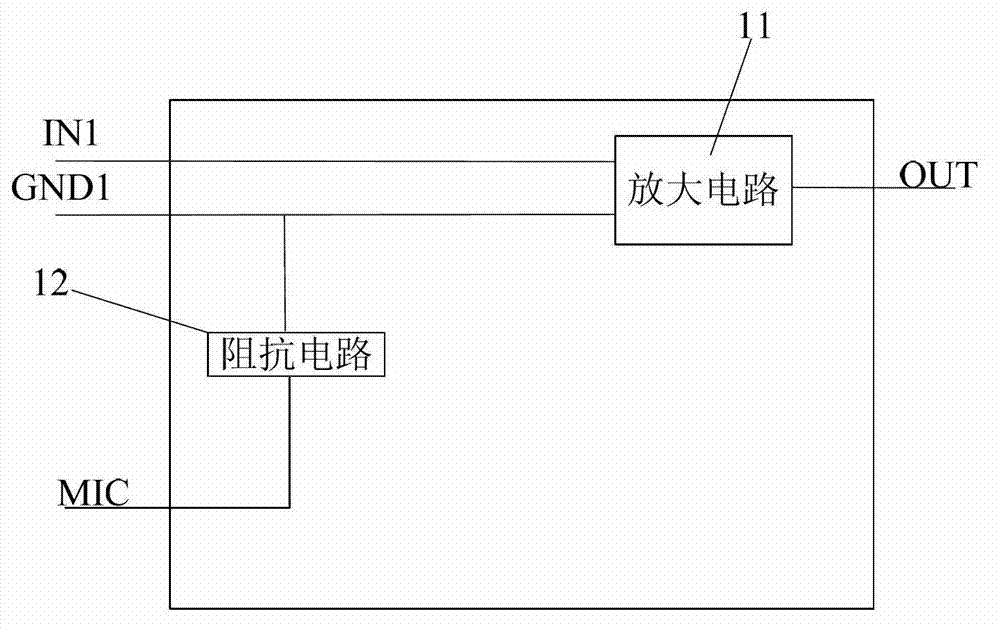
[0040] figure 1 It is the audio signal switching device of the present invention, see figure 1 , The audio signal conversion device includes: a first interface, a second interface, an audio signal amplifying circuit 11 and an impedance circuit 12 .
[0041]Wherein, the first interface includes an audio signal receiving pin IN1, a ground pin GND1 and a microphone pin MIC, wherein the audio signal receiving pin IN1 is a monophonic pin in a monophonic audio plug, or a stereo audio plug One of the left or right channel pins in the Since the positions of the ground pin GND1 and the microphone pin MIC have not been determined temporarily, the ground pin GND1 and the microphone pin MIC are interchangeable in the following descriptions. For the convenience of description, in this embodiment and other embodiments, all refer to figure 1 The positions of the ground pin GND1 and the microphone pin MIC are described in , which should not be understood as a limitation of the present inven...
Embodiment 2
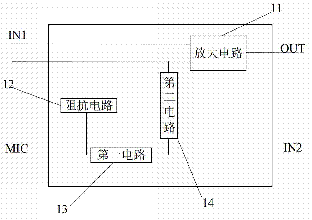
[0047] figure 2 is a structural schematic diagram of the audio signal switching device of the present invention, see figure 2 The difference between this embodiment and Embodiment 1 is that the second interface shown in Embodiment 1 may further include an audio signal input pin IN2. figure 2 The same parts as those in Example 1 have been given the same reference numerals. At the same time, the same numbering rules are also adopted for the following other embodiments.
[0048] Specifically, the audio signal conversion device further includes: a first circuit 13 and a second circuit 14 .
[0049] Wherein, the first circuit 13 is coupled between the microphone pin MIC and the audio signal input pin IN2, the second circuit 14 is coupled between the ground pin GND1 and the audio signal input pin IN2, the first circuit 13 and the second The two circuits 14 are mutually attenuating circuits.
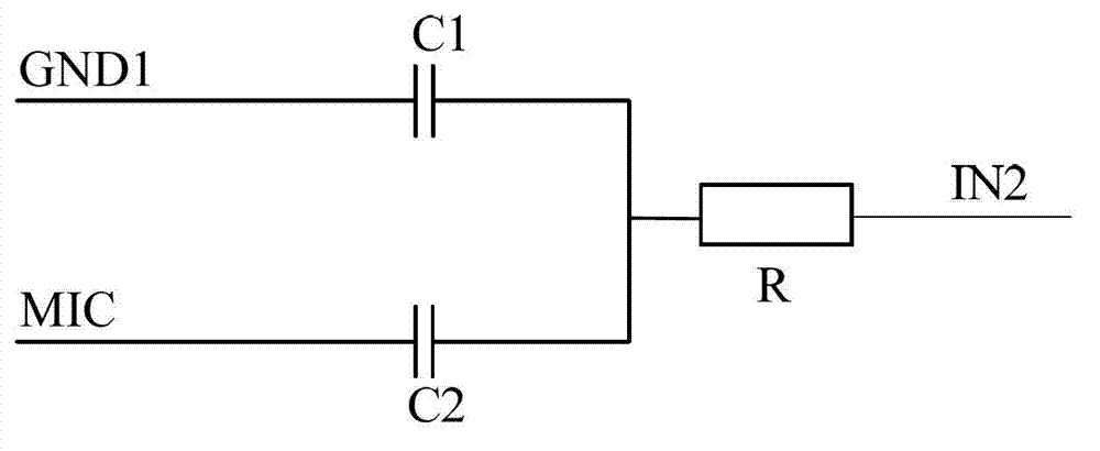
[0050] In addition, the first circuit 13 uses a filter circuit or a voltage divider ...
Embodiment 3
[0060] The audio signal amplifying circuit 11 mentioned in Embodiment 1 may include: a transformer, a resistor connected in parallel with an operational amplifier, an inductor connected in parallel with an operational amplifier, a resistor connected in parallel with a comparator, or an inductor connected in parallel with a comparator, etc.
[0061] The present invention will be described below by taking the transformer 11 as an example to amplify audio signals. refer to Figure 4 , the primary coil of the transformer 11 is connected to the audio signal receiving pin IN1 and the ground pin GND1, and the secondary coil of the transformer 11 is connected to the audio signal output pin OUT.
[0062] Since the transformer 11 is a passive device, it does not consume any power during operation.
[0063] In addition, using the transformer 11 to amplify the audio signal also solves the problem of common mode between interfaces of different devices.
[0064] The use of transformers fo...
PUM
 Abstract
Description
Claims
Application Information
 - Generate Ideas
- Intellectual Property
- Life Sciences
- Materials
- Tech Scout
- Unparalleled Data Quality
- Higher Quality Content
- 60% Fewer Hallucinations
Browse by: Latest US Patents, China's latest patents, Technical Efficacy Thesaurus, Application Domain, Technology Topic, Popular Technical Reports.
© 2025 PatSnap. All rights reserved.Legal|Privacy policy|Modern Slavery Act Transparency Statement|Sitemap|About US| Contact US: help@patsnap.com


