A main transformer low-voltage foil structure and its realization method

A low-voltage foil and foil winding technology, applied in the direction of inductor/transformer/magnet manufacturing, transformer/inductor coil/winding/connection, coil manufacturing, etc., can solve the problems of low efficiency and complicated winding, and reduce the helix angle , reduce unbalanced ampere-turns, reduce the effect of axial electromotive force

Active Publication Date: 2015-11-18
中电电气(江苏)变压器制造有限公司
View PDF4 Cites 0 Cited by
  • Summary
  • Abstract
  • Description
  • Claims
  • Application Information

AI Technical Summary

Problems solved by technology

The low voltage of the main transformer is generally a cylindrical, continuous or spiral structure, but these structures are complex in process and low in efficiency.

Method used


Image

  • A main transformer low-voltage foil structure and its realization method
  • A main transformer low-voltage foil structure and its realization method
  • A main transformer low-voltage foil structure and its realization method

Examples


Embodiment Construction

[0022] The present invention will be further explained below in conjunction with the accompanying drawings and specific embodiments.

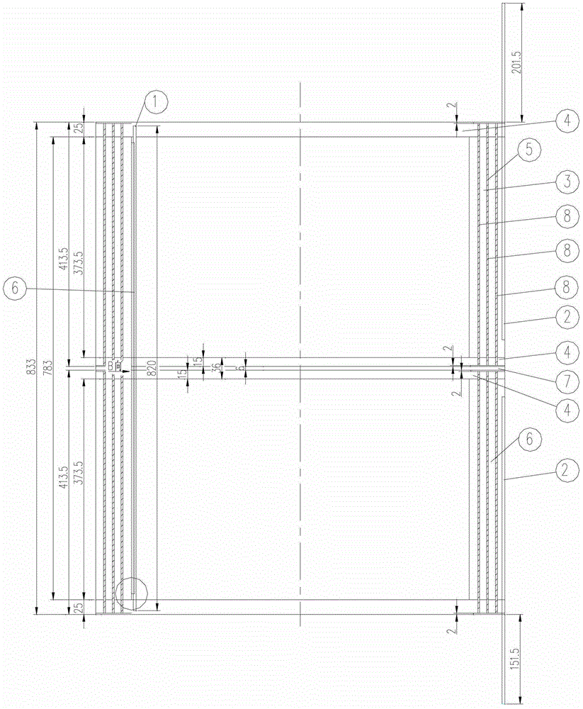
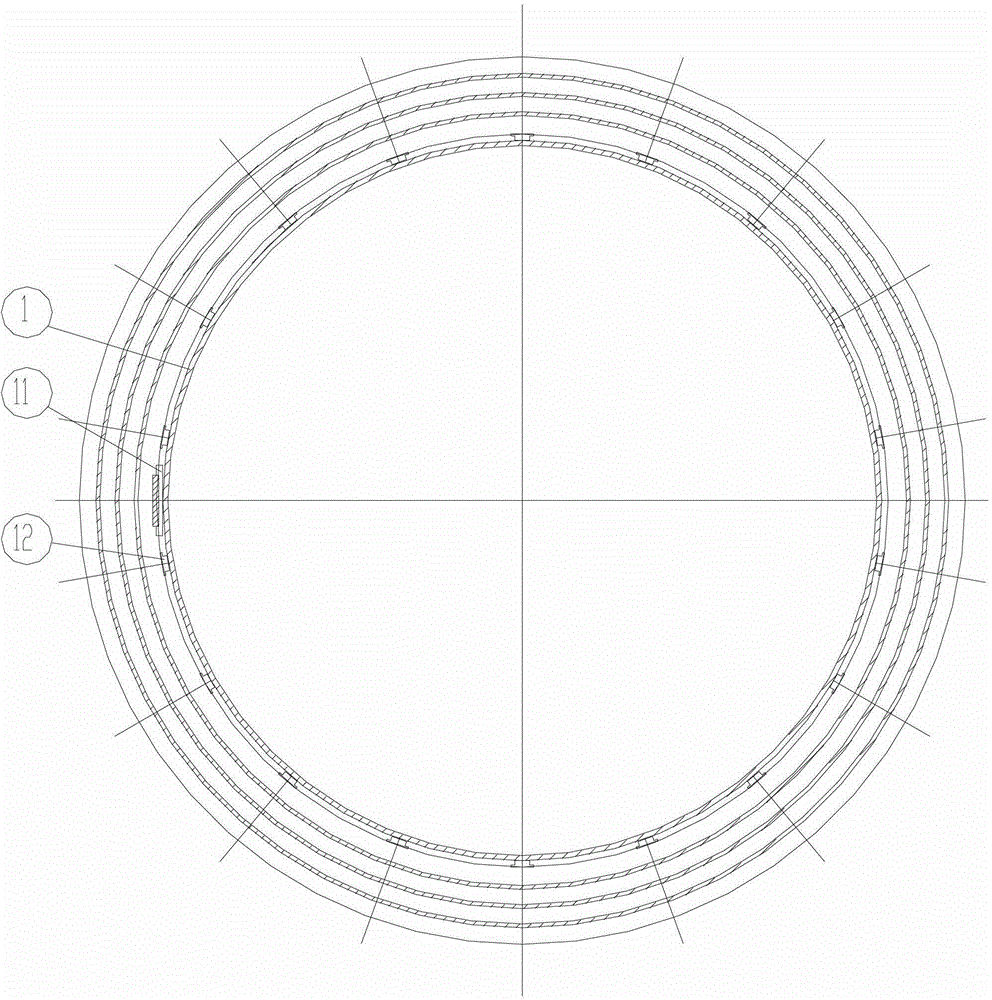
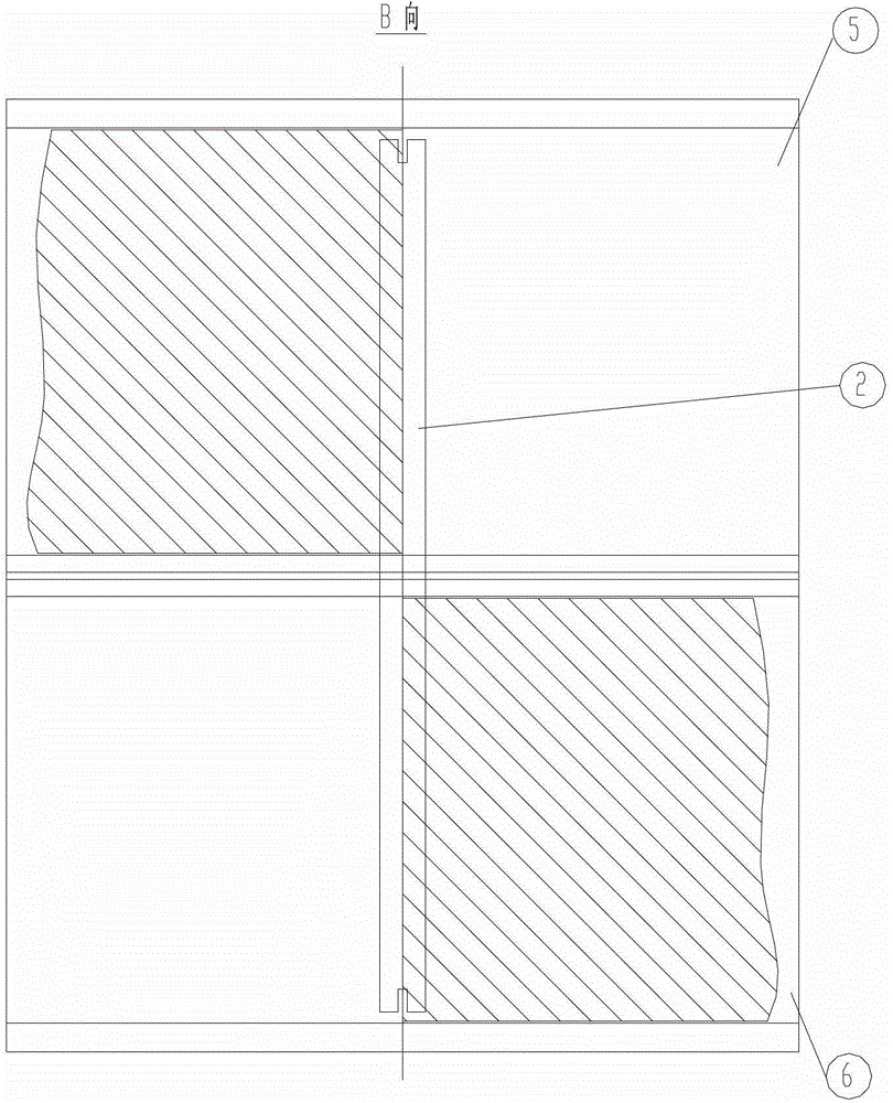
[0023] like Figure 1-4 As shown, the low-voltage foil structure of the main transformer includes an insulating paper tube 1 and a copper bar 2; the insulating paper tube is provided with two sections of foil windings 3 with the same winding direction, and each section of foil winding 3 is provided at both ends End insulation 4; the two sections of foil winding 3 are respectively the first section of foil winding 5 and the second section of foil winding 6; the first section of foil winding 5 and the second section of foil winding 6 are adjacent The insulating paper tube between the two ends of the insulation is provided with a first spacer 7, and the outer surface of the first spacer 7 is flush with the outermost layer foil winding 3; between each layer of foil winding 3 is provided The second spacer 8, wherein the second spacer 8 is provided ...


PUM


Abstract

The invention discloses a main transformer lower-voltage foil structure, which comprises an insulating paper cylinder and copper bars, wherein the insulating paper cylinder is provided with two segments of foil windings in the same winding direction; end insulators are arranged at the two ends of each segment of foil winding; the two segments of foil winding are respectively a first segment of foil winding and a segment of foil winding; a first cushion block is arranged on the insulating paper cylinder between the insulators at two adjacent ends of the first segment of foil winding and the second segment of foil winding; the outer surface of the first cushion block is flush with an outermost layer foil winding; a second cushion blocks is arranged between layers of foil windings; the second cushion block is provided with intervals on the copper bars; and the side faces of the two copper bars on the same side are provided with a paper plate respectively. The implementation method comprises the following steps of: sticking a brace to the insulating paper cylinder, partitioning the insulating paper cylinder into two segments, forming a gap between the two segments, and filling the first cushion block into the gap; arranging end insulators at the two ends of the two segments of foil windings; and arranging the second cushion block between the adjacent foil windings.

Description

technical field [0001] The invention relates to a low-voltage foil structure of a main transformer and a realization method thereof, and is mainly suitable for a low-voltage foil structure with a capacity of more than 25000kvA of a main transformer and a realization method thereof. Background technique [0002] In recent years, the foil structure has been widely used in small and medium-sized transformers, but it is still rare in the main transformer low-voltage foil structure. The low voltage of the main transformer is generally a cylindrical, continuous or spiral structure, but these structures are complex in process and low in efficiency. Contents of the invention [0003] Purpose of the invention: Aiming at the problems and deficiencies in the prior art, the present invention provides a low-voltage foil structure of the main transformer and its realization method, the so-called foil winding, that is, the coil is wound with copper or aluminum foil. Because the current ...

Claims


Application Information

Patent Timeline
Patent Type & Authority Patents(China)
IPC IPC(8): H01F27/30H01F27/32H01F41/06H01F41/063
Inventor 杨庆福陈忠
Owner 中电电气(江苏)变压器制造有限公司
Why Eureka
Try Eureka