Visual field eliminating rotation mechanism of horizontal telescope

A technology for rotating mechanisms and telescopes, applied in telescopes, optics, instruments, etc., can solve problems such as time delay, signal-to-noise ratio drop, complex structural design and adjustment, and achieve high rotation accuracy and high rotation positioning accuracy.

Inactive Publication Date: 2013-01-16
INST OF OPTICS & ELECTRONICS - CHINESE ACAD OF SCI
View PDF2 Cites 9 Cited by
  • Summary
  • Abstract
  • Description
  • Claims
  • Application Information

AI Technical Summary

Problems solved by technology

Optical derotation is to install a derotation prism along the optical axis in front of the imaging device, and physical derotation is to directly control the rotation of the CCD imaging device according to the optical axis of the system. These two methods directly offset the image rotation when it is generated, but Structural design and adjustment are relatively complicated
Electronic derotation is to use hardware processing to rotate digital images, and digital derotation is to use software algorithms to rotate digital images. Both of them are processed by algorithms, and there are problems such as time delay, image precision reduction, and signal-to-noise ratio reduction.

Method used


Image

  • Visual field eliminating rotation mechanism of horizontal telescope
  • Visual field eliminating rotation mechanism of horizontal telescope
  • Visual field eliminating rotation mechanism of horizontal telescope

Examples


Embodiment Construction

[0018] The present invention will be further described below in conjunction with the accompanying drawings and specific embodiments.

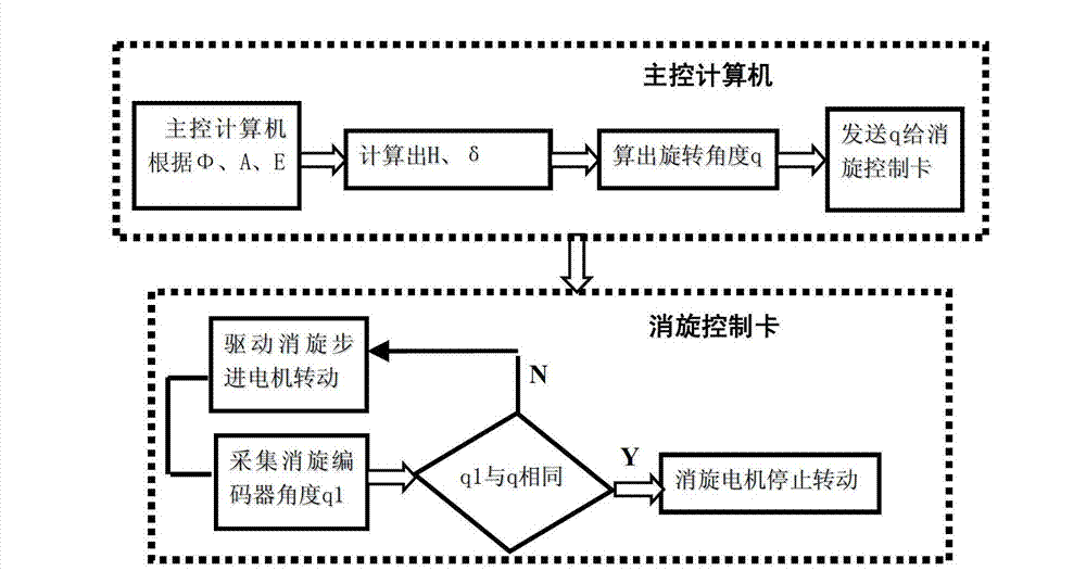
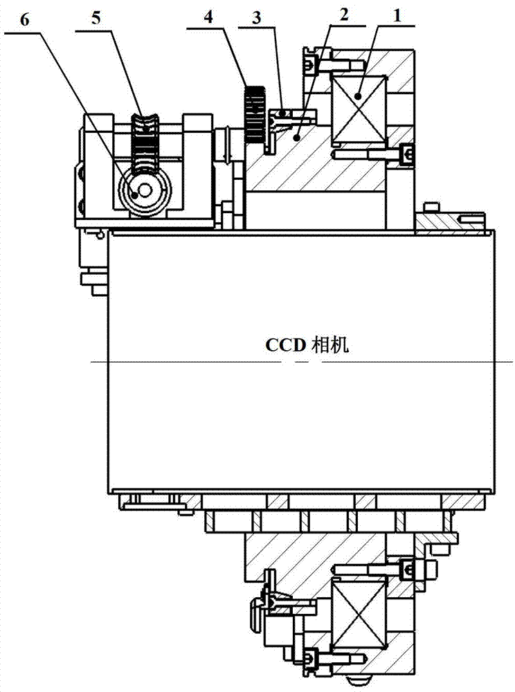
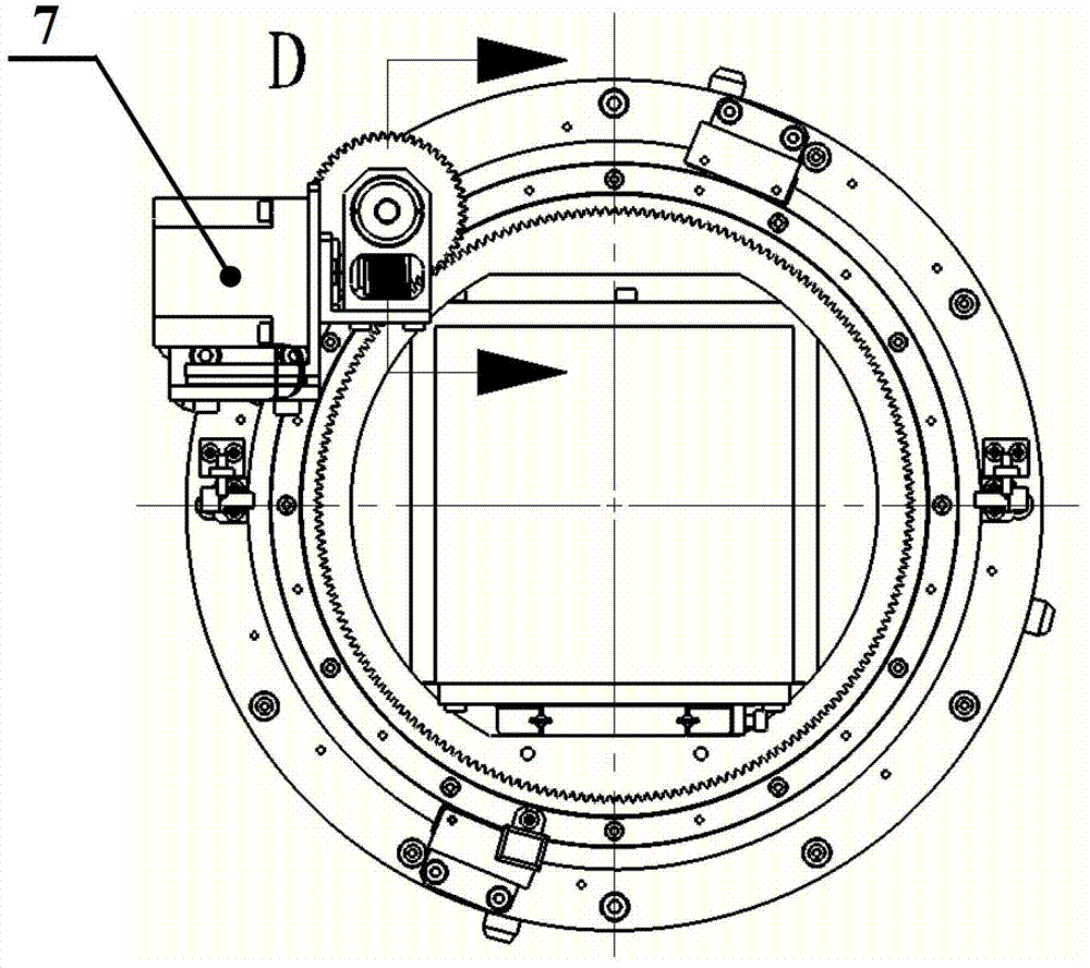
[0019] The invention provides a horizon-type telescope disappearing field rotating mechanism, which includes a cross roller bearing 1, a driven spur gear 2, a driving spur gear 4, a metal reflective circular grating encoder 3, a turbine 5, Worm screw 6, stepping motor 7 and CCD camera;

[0020] The stepper motor 7 is used to drive the worm 6, the worm 6 drives the turbine 5, the turbine 5 drives the driving spur gear 4, and the driving spur gear 4 drives the driven spur gear 2 to rotate to drive the CCD camera to rotate ; The drive and driven spur gears, the worm gear and the worm adopt two-stage transmission to achieve a larger transmission ratio;

[0021] The metal reflective circular grating encoder 3 is used for the measurement of the rotation angle during the rotation of the CCD camera;

[0022] The metal reflective circular grating enco...


PUM


Abstract

The invention provides a visual field eliminating rotation mechanism of a horizontal telescope. The visual field eliminating rotation mechanism comprises a cross roller bearing (1), straight toothed spur gears (2 and 4), a metal reflection type circular grating encoder (3), a worm wheel (5), a worm rod (6), a step motor (7) and a CCD (Charge Coupled Device) camera, wherein the encoder and the bearing are coaxially mounted; and the photosensitive surface of the CCD camera is perpendicular to a rotating shaft. When the telescope is in the process of tracking a fixed star, a rotation angle is calculated by a theoretical model of visual field rotation according to the real-time pointing positions of the telescope: an azimuth angle A and an angular altitude E, the mechanism is driven in real time to drive a CCD to rotate so as to eliminate the visual field rotation phenomenon in the process of tracking the fixed star by the horizontal telescope, the formed images of all the fixed stars on the CCD camera are clear point images all the time in integral time, and the star images are kept to be fixed all the time on a CCD detector. According to the visual field eliminating rotation mechanism, the bearing adopts the cross roller bearing, the metal circular grating is adopted to measure the angle in real time and perform position feedback in the rotation process, and higher rotation positioning precision can be obtained.

Description

technical field [0001] The invention relates to the technical field of horizon telescopes, in particular to a field-elimination rotating mechanism of horizon telescopes. Due to the advantages of simple structure, convenient processing and adjustment, and convenient installation in the field, many telescopes currently use the horizon type, especially large-scale telescopes. However, there is a problem of rotation of the field of view in the process of tracking stars in the horizon-level telescope, which makes the image of the stars acquired by the CCD camera blurred. The length of the integration time can ensure that the CCD can obtain clear star images. Background technique [0002] In the early days, due to the underdevelopment of computer technology, most telescopes used equatorial telescopes. The frame had two rotation axes perpendicular to each other. One rotation axis was parallel to the rotation axis of the earth, called the polar axis, and the other was perpendicular...

Claims


Application Information

Patent Timeline
Patent Type & Authority Applications(China)
IPC IPC(8): G02B23/12
Inventor 李晓燕庄富强王岱李艳平
Owner INST OF OPTICS & ELECTRONICS - CHINESE ACAD OF SCI
Why Eureka
Try Eureka