
Light guide plate and method for manufacturing the same

A manufacturing method and technology of a light guide plate, applied in the direction of light guides, optics, optical components, etc., can solve problems such as the inability to eliminate total reflection of light, increase the divergence angle of light incident on the light guide plate, etc.

Inactive Publication Date: 2013-01-16
DARWIN PRECISIONS CORP
View PDF2 Cites 5 Cited by
  • Summary
  • Abstract
  • Description
  • Claims
  • Application Information

AI Technical Summary

Problems solved by technology

However, such a structure can only increase the divergence angle of light incident on the light guide plate, and cannot eliminate the phenomenon of total reflection of light

Method used


Image

  • Light guide plate and method for manufacturing the same
  • Light guide plate and method for manufacturing the same
  • Light guide plate and method for manufacturing the same

Examples


Embodiment Construction

[0028] Below in conjunction with accompanying drawing, structural principle and working principle of the present invention are specifically described:

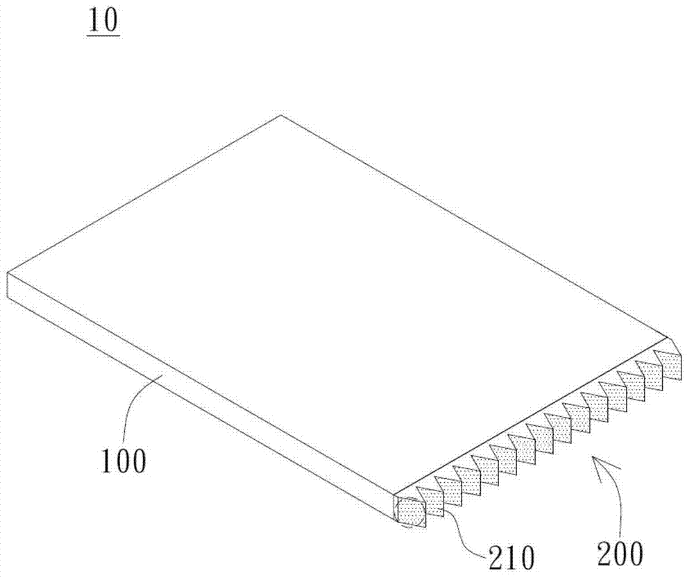
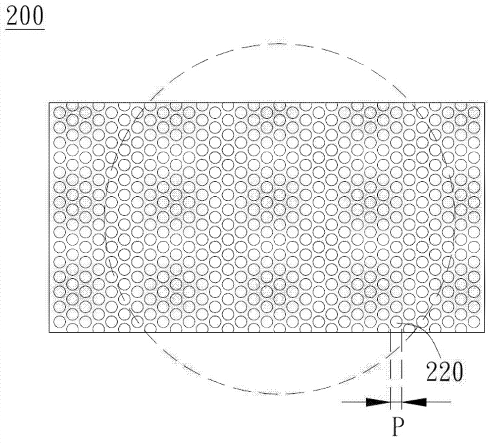
[0029] figure 1 It is a schematic diagram of an embodiment of the light guide plate of the present invention. Such as figure 1 As shown, the light guide plate 10 includes a main body 100 with a light incident side, a plurality of primary microstructures 210 disposed on the light incident side, and a plurality of secondary microstructures 220 distributed on the surfaces of the primary microstructures 210 (see image 3 , Figure 4 ).

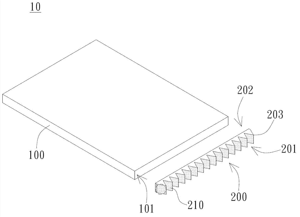
[0030] figure 2 for figure 1 3D exploded view of the light guide plate. Such as figure 2 As shown, the light guide plate 10 includes a main body 100 and a microstructure substrate 200 . The main body 100 has a light-incident side 101 for receiving light. The main body 100 can be fabricated by predetermined manufacturing methods, predetermined materials, and predetermined length, width, ...


PUM

PropertyMeasurementUnit
Angleaaaaaaaaaa
Biggest sizeaaaaaaaaaa

Abstract

The invention discloses a light guide plate and a method for manufacturing the same. The light guide plate comprises a main body possessing a light incoming side, a plurality of main micro-structures arranged at the light incoming side, and a plurality of secondary micro-structures distributed on the surfaces of the main micro-structures. The maximum size of the secondary micro-structures is greater than 0 nanometer and less than 100 nanometers. By utilizing the secondary micro-structures, the light full-reflection phenomenon can be reduced effectively, the loss when the light is radiated to the light guide plate is avoided; and by increasing the dissipation angle when the light is radiated to the light guide plate, the phenomenon can be relieved that light beams are concentrated at the front end of a light source to cause the light outgoing surface of the light guide plate to generate bright and dark belts.

Description

technical field [0001] The invention relates to a light guide plate and a manufacturing method thereof. Background technique [0002] In the existing backlight module, for example, a light-emitting diode is used as a side-illuminated light source structure as a point light source. In such a light source structure, since a plurality of LEDs are arranged at predetermined intervals, the light emitted by each LED forms a light beam directly in front of the LED. In contrast, the brightness between adjacent LEDs is relatively dark. When such light enters the light guide plate, bright and dark bands will be formed on the light emitting surface of the light guide plate. [0003] In this regard, in the prior art, concave grooves are provided on the light-incident side of the light guide plate to form a main microstructure such as a prism structure or a lens structure on the light-incident side, thereby increasing the divergence angle of light incident on the light guide plate and sl...

Claims


Application Information

Patent Timeline
IPC IPC(8): G02B6/00G02B5/04
Inventor 潘昆志胡清渊张忠兴
Owner DARWIN PRECISIONS CORP
Learn More