Method for detecting fluidity of slag in coal gasifier
A detection method and fluidity technology are applied in the detection field of slag fluidity in coal gasification furnaces to achieve the effects of improving measurement accuracy, performance and spatial resolution
- Summary
- Abstract
- Description
- Claims
- Application Information
AI Technical Summary
Problems solved by technology
Method used
Image


Examples
Embodiment 1
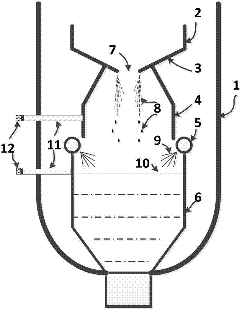
[0050] Such as figure 1 As shown, the structure of the lower part of the coal gasification device in this embodiment includes a pressure shell 1, a gasification chamber surrounded by a gasifier wall 2, a converging wall 3 at the bottom of the gasifier wall, a slag screen 4, a spray ring 5, Slag pond 6, lower slag outlet 7, spray water 9, slag pond liquid level 10. After the molten slag 8 comes out from the lower slag port 7, it falls freely under the action of gravity, falls into the slag pool 6, and quickly (cools) decomposes into dense glass-like small particles and flows downward into the slag pool at the bottom of the gasifier 6. Discharge after being crushed by a slag breaker. In order to remove the heat generated by solidification and cooling of the molten slag, the gray water in the slag pool 6 circulates in the slag pool 6 and is injected through the spray ring 5 on the slag pool 6 after being cooled by an external cooler. A large number of sounds will be emitted dur...
Embodiment 2
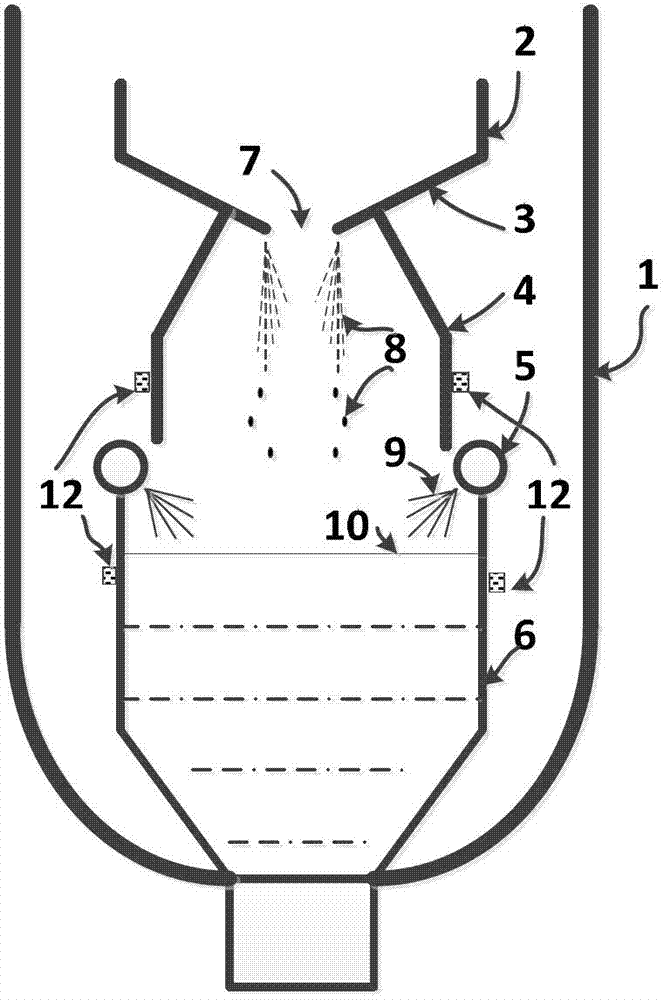
[0078] The experimental device of this embodiment is as figure 2 Shown, the difference with embodiment 1 is: 1, adopt such as figure 2 The arrangement of the acoustic wave receiving device shown in the figure: one end of the probe 11 is welded on the wall of the slag pool 6 and the wall of the slag screen 4, and the other end passes through the pressure shell 1 to connect the acoustic wave sensor 12, and is uniformly arranged in the circumferential direction in the slag pool 6 4 sets of acoustic wave sensors 12 and probes 11, 2 sets of acoustic wave sensors 12 and probes 11 are evenly arranged circumferentially above the slag pool 6;
[0079] 2. In this embodiment, an acceleration sensor is used to collect acoustic signals. The frequency response range of the acceleration sensor is 1-30KHz, the system sampling frequency is 200KHz, and the sampling time is 30s;
[0080] 3. Use E as a characteristic parameter to establish a prediction model. Other implementations are the sam...
Embodiment 3
[0082] The experimental device of this embodiment is as image 3 As shown, the difference from Example 1 is: using such as image 3 In the arrangement shown, no probe is used, the acoustic wave sensor 12 is directly attached to the outer wall surface of the slag pool 6 and the slag screen 4, and multiple acoustic wave sensors are respectively arranged above the slag pool and the slag pool. Other implementations are the same as in Example 1. The measured value F of the finally obtained slag fluidity index is 10.16, and the actual value F 0 is 10.08, and the relative deviation B is 0.79%.
[0083] In Example 1, Example 2 and Example 3, the viscosity of the molten slag can be controlled within ±5% of the target value, effectively avoiding the occurrence of slag plugging.
PUM
| Property | Measurement | Unit |
|---|---|---|
| viscosity | aaaaa | aaaaa |
Abstract
Description
Claims
Application Information
 - R&D
- Intellectual Property
- Life Sciences
- Materials
- Tech Scout
- Unparalleled Data Quality
- Higher Quality Content
- 60% Fewer Hallucinations
Browse by: Latest US Patents, China's latest patents, Technical Efficacy Thesaurus, Application Domain, Technology Topic, Popular Technical Reports.
© 2025 PatSnap. All rights reserved.Legal|Privacy policy|Modern Slavery Act Transparency Statement|Sitemap|About US| Contact US: help@patsnap.com