Eureka AIR delivers breakthrough ideas for toughest innovation challenges, trusted by R&D personnel around the world.

Canning vacuum water-controlling equipment

A vacuum and canned technology, applied in the field of canned vacuum water control equipment

Inactive Publication Date: 2013-01-16
胡海明
View PDF7 Cites 5 Cited by
  • Summary
  • Abstract
  • Description
  • Claims
  • Application Information

AI Technical Summary

Problems solved by technology

However, it still has some structural defects. The water control machine needs to be manually operated and rotated during production, and cannot be matched with the automatic seaming machine to form a coherent automatic production line equipment.

Method used


Image

  • Canning vacuum water-controlling equipment
  • Canning vacuum water-controlling equipment
  • Canning vacuum water-controlling equipment

Examples


Embodiment Construction

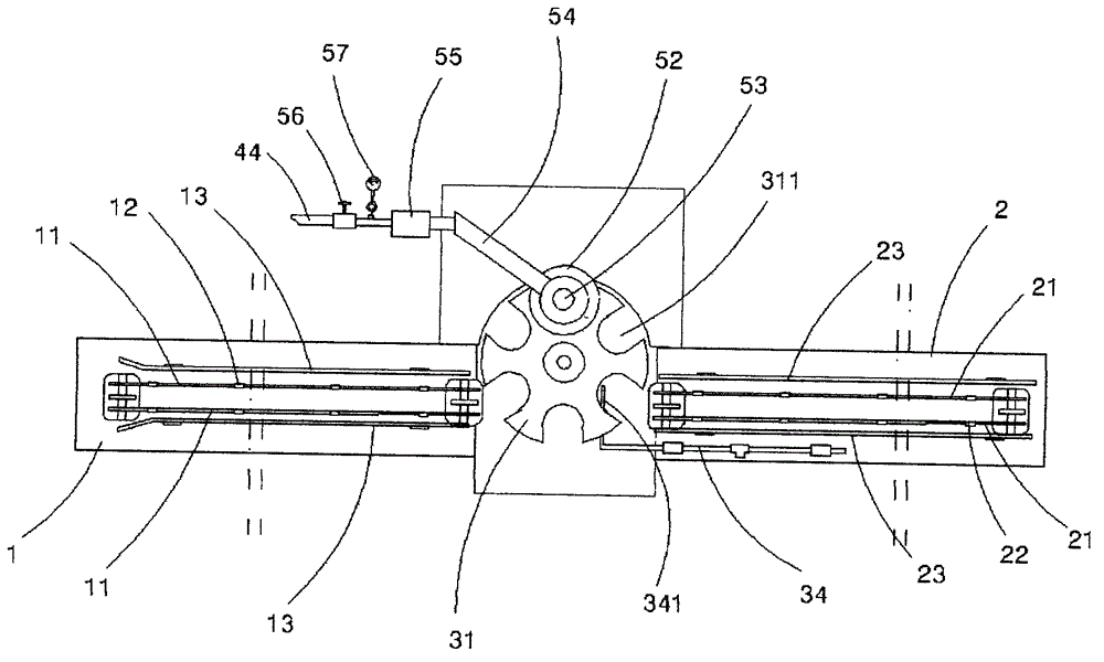
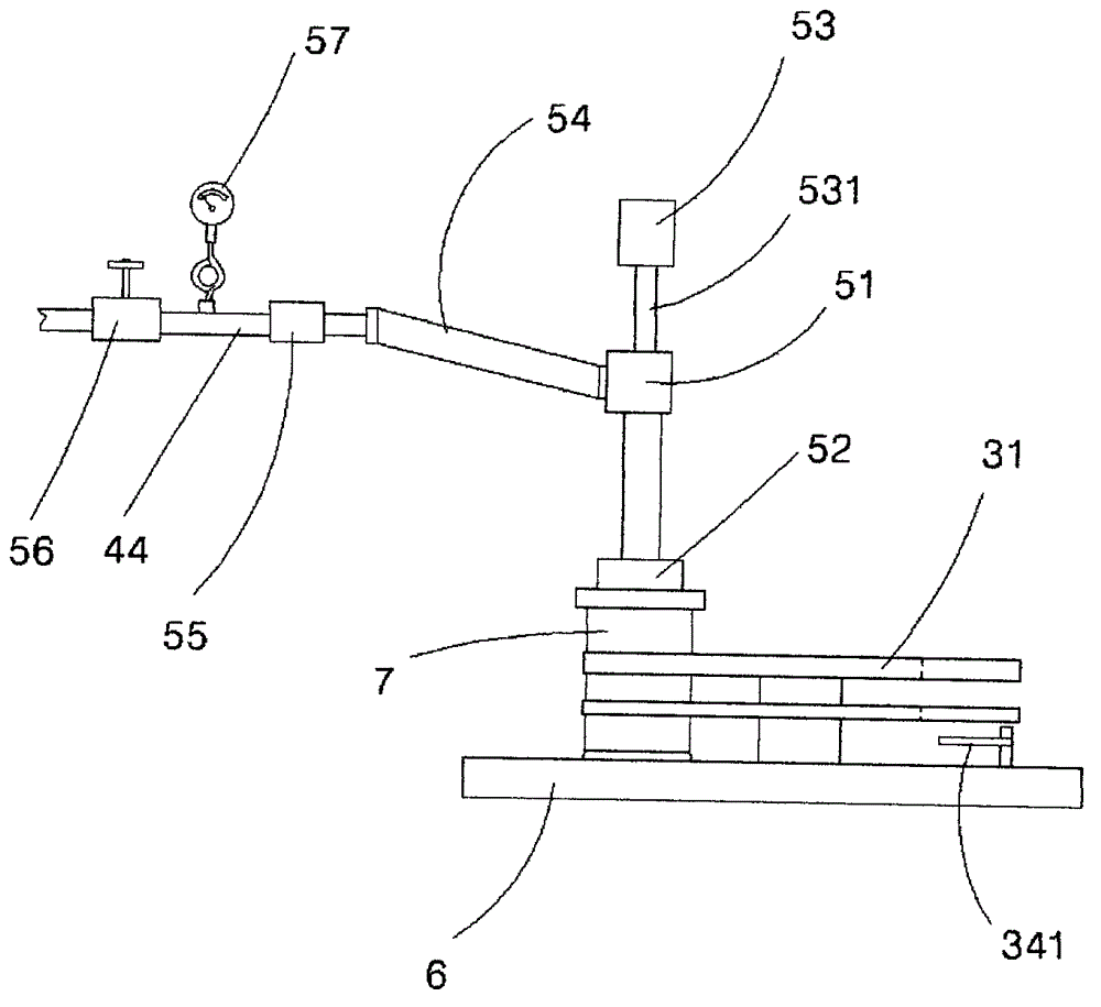
[0018] Such as figure 1 , 2 , 3, and 5, a canned vacuum water control device, including a tank-in conveyor frame 1, a tank-out conveyor frame 2, a vacuum stabilization device 4, a water absorbing device 5, and a transmission mechanism 3, and the tank-in conveyor frame 1 is Be provided with the conveying chain 11 that band pushes can claw 12, the both sides of conveying chain 11 are provided with retaining can bar 13; The side is provided with can retaining bar 23. The can-in carousel 31 of the transmission mechanism 3 is axially connected with the can-in conveyor frame 1 and the tank-out conveyor frame 2 on both sides, and their working platforms 6 are on the same horizontal plane. Arrange 6 tank position holes 311 for conveying the can body, the rotating shaft 32 of the tank feeding carousel is connected to the tank feeding eccentric wheel 33, the motor 38 drives the transmission shaft 37 to rotate, and the tank feeding eccentric wheel 33 on the transmission shaft 37 rotate...


PUM


Abstract

The invention relates to canning vacuum water-controlling equipment, which comprises a can entering conveying frame, a can exiting conveying frame, a vacuum stabilizing device, a water-sucking device and a transmission mechanism, wherein a can entering rotary disk of the transmission mechanism is axially connected with the can entering conveying frame and the can exiting conveying frame at both sides, a rotary shaft of the can entering rotary disk is connected with an can entering eccentric wheel to enable the can entering rotary disk to make intermittent-type rotary movement, the water-sucking device is positioned above the can entering rotary disk, a water-sucking pipe of the water-sucking device is axially connected with a cylinder and a pressure head, the upward and downward movement of the pressure head is synchronously matched with a can-position hole when the can entering rotary disk makes intermittent-type rotation, the vacuum stabilizing device comprises a vacuum pump and a vacuum can, the vacuum pump is connected with the vacuum can through a pipeline, a water-level sensor is arranged on the lateral wall of the vacuum can, a water-discharging electromagnetic valve is arranged at the bottom of the vacuum can, and a gas pipe which is led out of the vacuum can is connected with the water-sucking pipe of the water-sucking device. Water in a can is sucked out by adopting a vacuum water-sucking method in the invention, and the canning vacuum water-controlling equipment has the advantages of uniformity in water control, high speed and high benefit.

Description

technical field [0001] The invention relates to a food machine, in particular to a canned vacuum water control device for draining residual water in the can during the production process of canned food. Background technique [0002] In the traditional canned food production process, there is a draining process before the company calls, and personnel are arranged to drain the water in the canned cans one by one, especially in the production of canned fruits. After the contents are filled into empty cans , There is a lot of water in the tank. If the water in the tank is not drained, it is difficult to ensure the actual weight of the canned solids, and the sugar content is also difficult to control. Therefore, the operation of draining operation is indispensable, but this traditional operation method, production speed is slow, and personnel waste is big, and production efficiency can not be improved. [0003] In order to overcome the defects in the above-mentioned technologies...

Claims


Application Information

Patent Timeline
IPC IPC(8): B65B61/00
Inventor 胡海明
Owner 胡海明
Why Eureka
Eureka Blog
Learn More