Angle ejector rod with stress step

A technology of inclined ejector and steps, which is applied to the field of inclined ejectors with stressed steps, can solve the problems of decreased injection molding production efficiency, high maintenance cost, low production efficiency, etc., so as to improve the qualified rate of products, reduce maintenance costs, The effect of extended operating life

Active Publication Date: 2013-01-16
NINGBO FANGZHENG TOOL
View PDF6 Cites 2 Cited by
  • Summary
  • Abstract
  • Description
  • Claims
  • Application Information

AI Technical Summary

Problems solved by technology

[0003] In the actual operation of the injection mold, due to the inertia of the top plate reset, there will be an interference tension generated when the inclined ejector rod pulls the inclined ejector block back into the placement groove, and at the same time, a collision will occur when the bottom of the inclined ejector block contacts the bottom of the placement groove The impact force, the above-mentioned interference pulling force and impact force are all collected at the key pin connecting the inclined ejector rod and the inclined ejector block. Over time, the key pin tenon and key pin connecting the inclined ejector rod and the inclined ejector block will be damaged due to damage. In the event of the breakage of the slanting ejector and the separation of the slanting ejector block, it is necessary to stop the machine and dismantle the mold to replace the inclined ejector, which will increase the maintenance cost of the mold, reduce the production efficiency of injection molding, and increase the defect rate of the product. Therefore, the existing technology has high maintenance costs and low production efficiency. , Problems and deficiencies of low qualified rate of products

Method used


Image

  • Angle ejector rod with stress step
  • Angle ejector rod with stress step
  • Angle ejector rod with stress step

Examples


Embodiment Construction

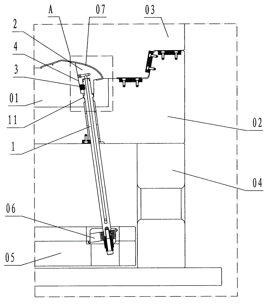
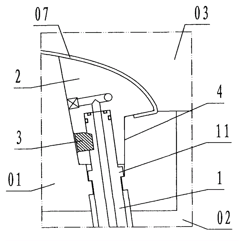
[0016] refer to figure 1 , figure 2 , a kind of inclined ejector rod provided with a stressed step of the present invention includes an inclined ejector rod 1 and a stressed step 11, and the inclined ejector rod 1 is a cylindrical step-shaped tubular steel member with a hollow cooling water channel in the center , the upper cylindrical surface of the inclined ejector rod 1 is provided with a circle of cylindrical flange steps called force steps 11;

[0017] Application connection, the upper end of the jacking rod 1 is inserted into the bottom hole of the jacking block 2, and is fixedly connected with each other by the key pin mortise of the jacking rod 1 and the jacking block 2 with the key pin 3. At this time, the force The step 11 is positioned below the bottom surface of the slanting top block 2; a step groove carrying the stressed step 11 is set at the bottom of the groove 4 of the moving model core 01 for slidingly arranging the slanting top block 2, and The groove bo...


PUM


Abstract

The invention discloses an angle ejector rod with a stress step. According to the technical scheme, the angle ejector rod with the stress step comprises an angle ejector rod body (1) and the stress step (11), wherein the stress step is arranged on a cylindrical surface of the angle ejector rod body and is positioned below a joint of the angle ejector rod body and an angle ejector block; a step groove for bearing the stress step is formed in the bottom of an accommodating groove of a moving mold core; and during working, interference tension and impact force which are generated by resetting inertia of an ejector plate are born by the stress step, so that a key pin rabbet and a key pin which are used for connecting the angle ejector rod body and the angle ejector block are protected against being damaged. The shortcomings of high maintenance cost, low production efficiency and low yield of products in the prior art are overcome. The force damaging the key pin rabbet and the key pin which are used for connecting the angle ejector rod body and the angle ejector block is born by the stress step, so that the aims of reducing maintenance cost, increasing production efficiency and increasing the yield of the products are achieved during production and running of an injection mold.

Description

technical field [0001] The invention relates to an inclined ejector part of an injection mold, in particular to an inclined ejector provided with a force-bearing step for supporting an inclined ejector block of an injection mold to perform ejection of an inclined ejector core. Background technique [0002] The inclined ejector rod is a component used to support the inclined ejector block for the injection mold to carry out inclined ejector core-pulling and demoulding. The inclined ejector rod in the prior art is a cylindrical rod-shaped steel member. When applying it, refer to image 3 , the upper end of the inclined ejector rod is connected with the inclined ejector block provided with the profile of the molded product through a key pin, and the inclined ejector block is slidably embedded in the placement groove of the moving model core, and the lower end of the inclined ejector rod is connected with the sliding foot of the sliding foot pair, The sliding seat of the sliding ...

Claims


Application Information

Patent Timeline
Patent Type & Authority Applications(China)
IPC IPC(8): B29C45/33B29C45/40
Inventor 丁宏参方永杰
Owner NINGBO FANGZHENG TOOL
Why Eureka
Try Eureka