
Side-exhaust exhaust valve bonnet

A technology of exhaust valve and bonnet, which is applied in the field of pressure cooker, can solve problems such as burns, and achieve the effect of reducing pressure, low cost, and reducing the risk of burns

Inactive Publication Date: 2013-01-16
袁振华
View PDF5 Cites 4 Cited by
  • Summary
  • Abstract
  • Description
  • Claims
  • Application Information

AI Technical Summary

Problems solved by technology

[0003] However, when the existing exhaust valve is exhausted, the gas is directly ejected from the top of the valve cap, and the user is still easily burned if he is not careful, so this structure needs further improvement

Method used


Image

  • Side-exhaust exhaust valve bonnet
  • Side-exhaust exhaust valve bonnet
  • Side-exhaust exhaust valve bonnet

Examples


Embodiment

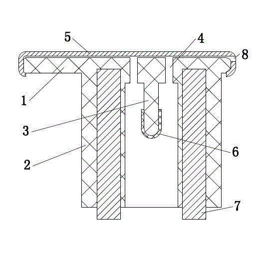
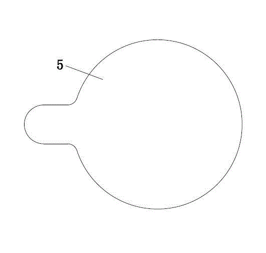
[0019] Such as figure 1 , figure 2 with image 3 The bonnet of an exhaust valve with side exhaust is shown, including a bonnet part 1, a valve body part 2, and a thimble part 3, wherein the bonnet part 1 is provided with an exhaust hole 4, and a gland is set on the bonnet part 1 5. A rectangular air outlet 8 is provided on the side of the gland 5 .

[0020] Wherein, the gland 5 is food-grade silica gel. The bonnet part 1, the valve body part 2, and the thimble part 3 are integrated, and the outside of the thimble part 3 is wrapped with a rubber sleeve 6. A counterweight steel core 7 is embedded in the valve body 2, which is convenient for production and assembly.

[0021] When this embodiment is in use, the gas is discharged from the exhaust hole 4, but due to the obstruction of the gland 5, the gas cannot be directly ejected upwards, but is ejected from the air outlet 8 on the side of the gland 5 to the side. Due to the increased flow distance of the gas, it can not onl...


PUM


Abstract

The invention belongs to the technical field of pressure cookers and discloses a side-exhaust exhaust valve bonnet which comprises a bonnet (1), a valve body (2) and an ejector pin (3). The bonnet is provided with an air outlet (4). The side-exhaust exhaust valve bonnet is characterized in that a pressure cap (5) is sleeved on the top of the bonnet, and the side of the pressure cap is provided with exhaust holes. When the side-exhaust exhaust valve bonnet is used, gas is exhausted from the exhaust holes. Under the blocking action of the pressure cap (5), the gas is not directly spouted up but laterally spouted from the exhaust holes on the side of the pressure cap. In the process of spouting, flowing distance of the gas is increased, so that gas temperature can be lowered while gas pressure can be decreased. The gas is spouted from the side, so that the risk of scalding a user is reduced.

Description

technical field [0001] The invention belongs to the technical field of pressure cookers, and in particular relates to a side exhaust valve bonnet on a pressure cooker. Background technique [0002] Exhaust valves of existing pressure cookers or electric pressure cookers generally include a spool and a bonnet. When the pressure in the pressure cooker exceeds a certain value, the high-pressure gas pushes up the thimble and the valve cap, or when the valve cap is pulled up manually, the gas in the pot is discharged from the vent hole. It not only plays the role of safety protection, but also can be used for manual exhaust and pressure reduction. [0003] However, when the existing exhaust valve is exhausted, the gas is directly ejected from the top of the valve cap, and the user is still easily burned if he is not careful, so this structure needs further improvement. Contents of the invention [0004] In order to solve the above-mentioned problems in the prior art, the pres...

Claims


Application Information

Patent Timeline
IPC IPC(8): A47J27/09
Inventor 黄树才
Owner 袁振华
Learn More