Circuit for improving energy transmission efficiency of non-contact type IC (integrated circuit) card

A kind of energy transmission efficiency, non-contact technology, applied in the direction of output power conversion device, circuit device, emergency protection circuit device, etc., can solve the problem of not reaching the best matching, etc., to achieve the load capacity and adapt to the field strength range enhancement , to avoid the effect of card damage

Active Publication Date: 2013-01-09
TSINGHUA UNIV
View PDF3 Cites 11 Cited by
  • Summary
  • Abstract
  • Description
  • Claims
  • Application Information

AI Technical Summary

Problems solved by technology

According to the data, the currently designed matching circuit is mainly realized by directly connecting a resonant capacitor in parallel with the antenna end. This kind of matching is relatively simple to implement, but it does not achieve the best matching. For ordinary contactless cards (lower power consumption) This matching method can meet the requirements, but for the application of financial IC card (large power consumption), when the magnetic field strength is 1.5A / m (the minimum value specified in the ISO / IEC14443-2 standard), the coupled energy is no longer able to provide proper circuit operation

Method used


Image

  • Circuit for improving energy transmission efficiency of non-contact type IC (integrated circuit) card
  • Circuit for improving energy transmission efficiency of non-contact type IC (integrated circuit) card
  • Circuit for improving energy transmission efficiency of non-contact type IC (integrated circuit) card

Examples


Embodiment Construction

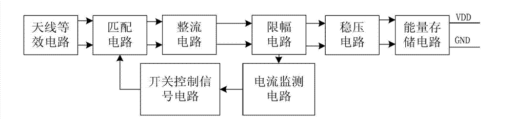
[0019] figure 1 It is a schematic diagram of the logical structure of the present invention. The antenna generates current under inductive coupling, the output end of the matching circuit is connected to the input end of the rectification circuit, the output end of the rectification circuit is connected to the input end of the limiting circuit, the output end of the limiting circuit is connected to the input end of the voltage stabilizing circuit, The output end of the voltage stabilizing circuit is connected to the input end of the energy storage circuit, the output end of the energy storage circuit is connected to the load, the output end of the limiting circuit is connected to the input end of the current monitoring circuit, and the output end of the current monitoring circuit is connected to the switch control signal circuit. The input ends are connected, and the output end of the switch control signal circuit is connected with the input end of the matching circuit.

[00...


PUM


Abstract

The invention relates to a circuit for improving energy transmission efficiency of a non-contact type IC (integrated circuit) card, belonging to the technical field of energy transmission circuits of high-current passive systems. The circuit is characterized by sequentially comprising a matching circuit, a rectifier circuit, a voltage-stabilizing and amplitude-limiting circuit, an energy storage circuit, a current monitoring circuit and a switch control circuit, wherein the matching circuit comprises a plurality of capacitors and a switch, and is used for obtaining best matching; the rectifier circuit comprises a plurality of MOS (metal oxide semiconductor) transistors and is used for converting alternating current voltage to direct current voltage; the voltage-stabilizing and amplitude-limiting circuit comprises a plurality of voltage-stabilizing units and amplitude-limiting units and is used for stabilizing the direct current voltage output by the last stage; the energy storage circuit comprises an energy storage capacitor and is used for storing energy when the field strength is reduced; and the switch control circuit comprises a current reproduction tube and a comparator and is used for controlling a switch in the matching circuit. The circuit disclosed by the invention can improve the energy transmission efficiency by automatically adjusting the matching circuit under the situations of low field strength and large load, can meet the requirements of the non-contact type IC card with a larger load, and can be applied to power supply for all modules in smart IC cards such as a financial IC card and the like.

Description

technical field [0001] The invention relates to an energy transmission circuit applicable to a large current passive system of a non-contact IC card such as an intelligent IC card, which relates to a matching circuit, a rectification circuit, an energy storage circuit, a voltage stabilizing and limiting circuit, current monitoring and switch control circuit design. technical background [0002] With the advancement of technology, non-contact IC cards are more and more widely used. In applications that require higher computing power and security, the internal power consumption of non-contact IC cards has increased significantly. Since most of the non-contact IC cards are passive, the power supply energy during operation is obtained by electromagnetic coupling from the magnetic field emitted by the card antenna from the card reader antenna. Therefore, the energy coupling efficiency determines the maximum power consumption that the contactless card can provide. The decisive f...

Claims


Application Information

Patent Timeline
Patent Type & Authority Applications(China)
IPC IPC(8): H02J17/00H02M7/217H02H7/125H02J50/12
Inventor 乌力吉王蓓蓓张向民
Owner TSINGHUA UNIV
Why Eureka
Try Eureka