
Device and method for measuring parallel core foam flooding gas-phase shunt volume

A technology of gas phase split flow and foam generating device, which is applied in the direction of measuring device, volume measuring instrument/method, measuring capacity, etc., and can solve the problem that the volume cannot be directly measured

Active Publication Date: 2013-01-09
CHINA UNIV OF PETROLEUM (EAST CHINA)
View PDF4 Cites 32 Cited by
  • Summary
  • Abstract
  • Description
  • Claims
  • Application Information

AI Technical Summary

Problems solved by technology

There is also a big difference between the two measurement methods. The liquid sub-flow can be directly measured. Because the gas is compressible, its volume cannot be measured directly. Therefore, the measurement of the gas sub-flow requires a certain experimental device to be realized.

Method used


Image

  • Device and method for measuring parallel core foam flooding gas-phase shunt volume
  • Device and method for measuring parallel core foam flooding gas-phase shunt volume
  • Device and method for measuring parallel core foam flooding gas-phase shunt volume

Examples


Embodiment 1

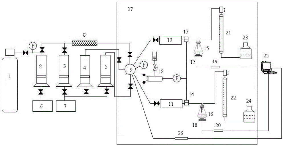
[0045] Such as figure 1 shown.

[0046] A device for measuring the fractional flow rate of the foam-driven gas phase in parallel rock cores, comprising a foam generating device, an intermediate container 4 for holding formation water, an intermediate container 5 for holding crude oil, a constant temperature box 27, a core tube 10, a core tube 11 and a data acquisition system The core tube 10 and the core tube 11 are installed in parallel in the thermostat 27; the foam generating device, the intermediate container 4 for holding formation water, and the intermediate container 5 for holding crude oil pass through the six-way valve respectively 9 is connected with the entrance of rock core pipe 10 and rock core pipe 11; Described data acquisition system comprises the pressure sensor 26 that links to each other with computer 25, load cell 19 and load cell 20, and described pressure sensor 26 is installed in six-way The valve 9 is the core pipe 10 and the inlet end of the core pipe...

Embodiment 2

[0049] A method for measuring the fractional flow rate of the foam-driven gas phase of parallel cores by using the above-mentioned device, comprising the following steps:

[0050] The required conditions of the method for measuring the gas phase saturation of the parallel core foam flooding are: the density of the foaming agent solution is equal to the density of the formation water; the partial flow rate of the gas phase at the outlet end of the parallel core is the flow rate under the standard atmospheric pressure of 0.1 MPa.


PUM

PropertyMeasurementUnit
Permeabilityaaaaaaaaaa

Abstract

The invention relates to a device for measuring parallel core foam flooding gas-phase shunt volume. The device mainly comprises a foam generating device, an intermediate container for containing formation water, an intermediate container for containing crude oil, a thermostat, core barrels and a data acquiring system, wherein weighing sensors are arranged at the bottom of produced liquid collectors, and are used for monitoring the weight of separated liquid of outlets of the core barrels; and wide-mouth bottles are connected with the produced liquid collectors through gas meters. By the device, the gas-phase shunt volume of parallel cores can be independently measured in real time in a parallel core foam flooding process. Produced liquid at outlet ends of the parallel cores is subjected to gas-liquid separation, and the gas-phase shunt volume of the outlet ends of the parallel cores is measured by using a specific device. Moreover, the device can also be used for measuring the weight of separated liquid of the outlets of the parallel cores, and profile control shunt conditions of foam on high and low permeable formations in the parallel cores under different injection rates can be analyzed by combing liquid injection quantity and change of pressure at two ends of each of the parallel cores.

Description

technical field [0001] The invention relates to a device and a method for measuring the fractional flow rate of the foam-driven gas phase of parallel rock cores, and belongs to the technical field of petrochemical industry. Background technique [0002] Foam has a high apparent viscosity in the formation, defoams when it meets oil, is stable when it meets water, has selective sealing ability for oil and water, and has higher seepage resistance in parts with higher water saturation. The resistance factor increases with the permeability. Therefore, it can effectively block the medium and high permeability parts and improve the sweep coefficient. At the same time, the foaming agent is generally a surfactant with excellent performance, which can reduce the oil-water interfacial tension to a certain extent. Therefore, foam control and flooding can not only improve the sweep efficiency, but also increase the oil displacement efficiency, and it is a promising method for enhancing o...

Claims


Application Information

Patent Timeline
IPC IPC(8): G01F22/02G01N7/10
Inventor 李松岩李兆敏张东李宾飞张超
Owner CHINA UNIV OF PETROLEUM (EAST CHINA)
Learn More