
Fireproof hydraulic control device

A control device and hydraulic technology, applied in the direction of valve device, valve operation/release device, functional valve type, etc., can solve the problems of aggravating accidents, easy to generate electric sparks, hidden safety hazards, etc. Force limit, stable and reliable installation

Active Publication Date: 2013-01-09
ZHEJIANG TIANTAI CONTROL EQUIP CO LTD
View PDF4 Cites 4 Cited by
  • Summary
  • Abstract
  • Description
  • Claims
  • Application Information

AI Technical Summary

Problems solved by technology

When the outside world is in an emergency state, such as a fire scene, the electromagnetic control mechanism is prone to power failure, signal failure, or even burnt out in this similar environment, making the electromagnetic control mechanism paralyzed and unable to control the opening and closing action of the valve. , which eventually exacerbated the occurrence of the accident
In addition, when the electromagnetic control mechanism is working, it needs to send and receive the corresponding induction electrical signals, which is easy to generate electric sparks. If it is used in oil refining and flammable and explosive areas, it is very likely to cause an explosion, which poses a great safety hazard.
In addition, when the existing electronically controlled hydraulic valves work for a long time, the magnetic properties of the electromagnetic coils in the electromagnetic control mechanism will often decrease due to the aging of the electromagnetic coil, resulting in the valve opening and closing not in place, and the use effect is not ideal.
In addition, the existing electronically controlled hydraulic valve has low anti-pollution ability. When it is polluted by water stains, oil stains, etc., it may cause the electromagnetic control mechanism to fail, greatly reducing the stability of the automatic control of the hydraulic valve. The electromagnetic control mechanism of the type hydraulic valve is relatively large in size and does not have explosion-proof capability, so it is inconvenient to use

Method used


Image

  • Fireproof hydraulic control device
  • Fireproof hydraulic control device
  • Fireproof hydraulic control device

Examples


Embodiment Construction

[0021] The present invention will be further described below in conjunction with accompanying drawing:

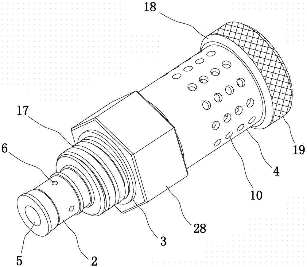
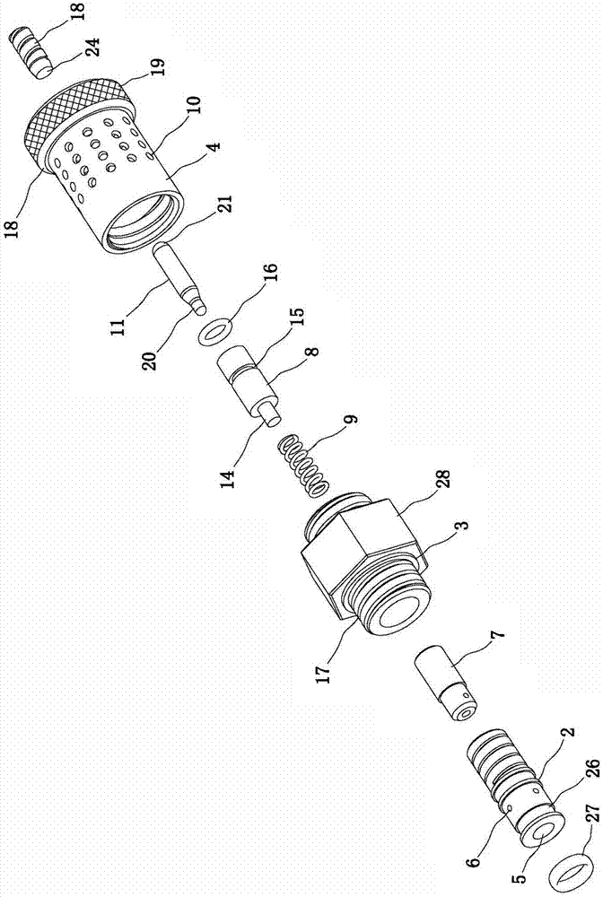
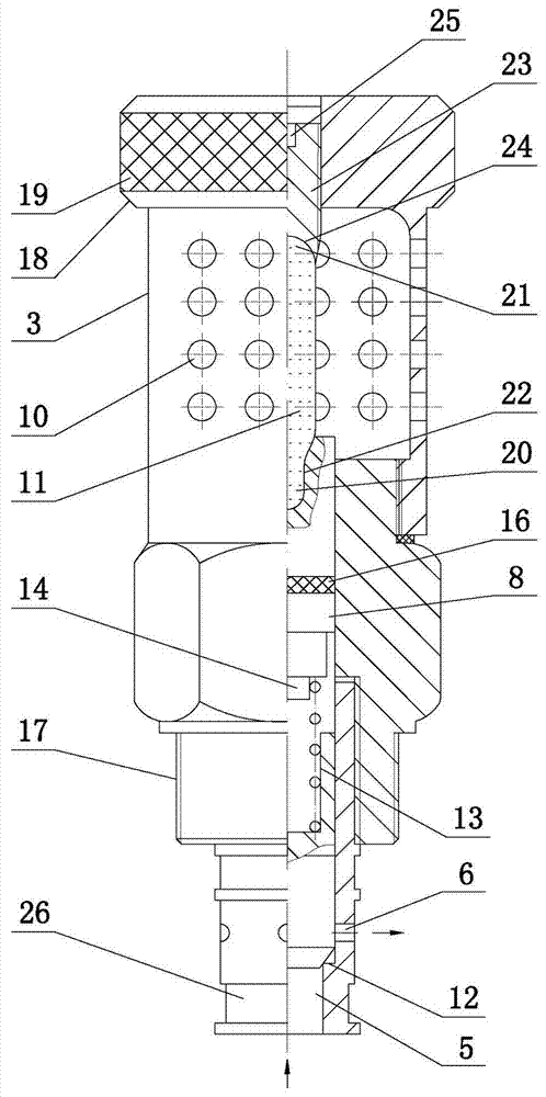
[0022] Referring to the accompanying drawings: the fire prevention hydraulic control device in this embodiment includes a hollow cylinder 2 connected to the oil circuit 1 of the hydraulic valve. There is a cover 4; the hollow cylinder 2 is provided with a liquid inlet 5 and a liquid outlet 6, and the inner cavity of the hollow cylinder 2 is provided with a spool 7 for closing the liquid inlet 5 and the liquid outlet 6; the mounting seat 3 There is a movable guide rod 8 inside, and a spring 9 is supported between the movable guide rod 8 and the valve core 7; a group of through holes 10 are arranged on the wall of the casing 4, and a temperature-sensitive glass ball 11 is arranged inside the casing 4, and the sensor One end of the warm glass ball 11 is against the movable guide rod 8, and the other end is against the inner end surface of the casing 4.

[0023] The inner wall...


PUM


Abstract

A fireproof hydraulic control device comprises a hollow column body connected to a hydraulic valve oil path, wherein a mounting seat is tightly connected with the upper end of the hollow column body; an encloser is arranged at the upper end of the mounting seat; a liquid inlet and a liquid outlet are arranged on the hollow column body; a valve core for sealing the liquid inlet and the liquid outlet is movably arranged in an inner cavity of the hollow column body; a movable guide rod is arranged in the mounting seat; a spring is supported between the movable guide rod and the valve core; a group of through holes are arranged on the wall of the encloser; a temperature sensing glass ball is arranged inside the encloser; one end of the temperature sensing glass ball abuts against the movable guide rod; and the other end of the temperature sensing glass ball abuts against the inner end face of the encloser. The control device can effectively control on / off of the oil path of the hydraulic valve if a fire hazard occurs all around when the fireproof hydraulic control device is applied to the environments of petroleum, gas and other inflammable and explosive articles. The hydraulic valve is enabled to be opened or closed in an extremely short time, so that an accident is further avoided. The fireproof hydraulic control device is small in size, convenient to install, strong in anti-pollution capacity, high in sensitivity, fast in response, high in stability, safe and reliable, can be repeatedly used and is worth popularizing.

Description

technical field [0001] The invention relates to a fire-proof hydraulic control device, in particular to a fire-proof hydraulic control device which can automatically control the opening and closing of a valve when a fire occurs in the working environment of a hydraulic valve system. Background technique [0002] A hydraulic valve is an automatic component operated by pressure oil. It is controlled by the pressure oil of the pressure distribution valve. It is usually used in combination with an electromagnetic pressure distribution valve. It can be used to remotely control the on-off of oil, gas, and water pipeline systems in hydropower stations. [0003] Existing electronically controlled hydraulic valves are all made up of parts such as valve body, spool, valve stem and electromagnetic control mechanism. Among them, the electromagnetic control mechanism is the control part of the opening and closing action of the electronically controlled hydraulic valve, which realizes the...

Claims


Application Information

Patent Timeline
Patent Type & Authority Applications(China)
IPC IPC(8): F16K17/38F16K31/64F16K41/02
Inventor 张德贤张中良
Owner ZHEJIANG TIANTAI CONTROL EQUIP CO LTD
Learn More