Pressure limiting and air leaking auxiliary brake valve device with supporting guide sleeve

A technology of auxiliary brake and valve device, which is applied in the direction of engine control, machine/engine, mechanical equipment, etc., which can solve the problem of the inability of the inner cavity of the pressure regulating device to dissipate heat, the delay of the braking effect of the auxiliary brake valve, and the inability to effectively control the exhaust Problems such as back pressure can be effectively controlled, the exhaust back pressure can be improved, and the resistance is small.

Inactive Publication Date: 2013-01-02
ZHEJIANG EASUN PNEUMATIC SCI & TECH
View PDF10 Cites 0 Cited by
  • Summary
  • Abstract
  • Description
  • Claims
  • Application Information

AI Technical Summary

Problems solved by technology

When the butterfly plate is closed and the engine exhaust gas is discharged into the intake chamber of the valve body, a part of the gas will inevitably enter the housing of the pressure regulating device, which hinders the reciprocating movement of the tappet and cannot effectively control the exhaust back pressure.
At the same time, due to the high temperature of the exhaust gas of the engine, the closed structure prevents the inner chamber of the pressure regulating device from dissipating heat, and the continuous high temperature will cause the pressure limiting spring to be deformed by heat, or even fail, and the braking effect of the auxiliary brake valve is seriously delayed, and the sensitivity is greatly reduced

Method used


Image

  • Pressure limiting and air leaking auxiliary brake valve device with supporting guide sleeve
  • Pressure limiting and air leaking auxiliary brake valve device with supporting guide sleeve
  • Pressure limiting and air leaking auxiliary brake valve device with supporting guide sleeve

Examples


Embodiment Construction

[0031] Several preferred embodiments of the present invention will be described in detail below with reference to the accompanying drawings, but the present invention is not limited to these embodiments. The present invention covers any alternatives, modifications, equivalent methods and schemes made on the spirit and scope of the present invention. In order to provide the public with a thorough understanding of the present invention, specific details are set forth in the following preferred embodiments of the present invention, but those skilled in the art can fully understand the present invention without the description of these details. In addition, well-known methods, procedures, processes, components, etc. have not been described in detail in order to avoid unnecessary confusion to the essence of the present invention.

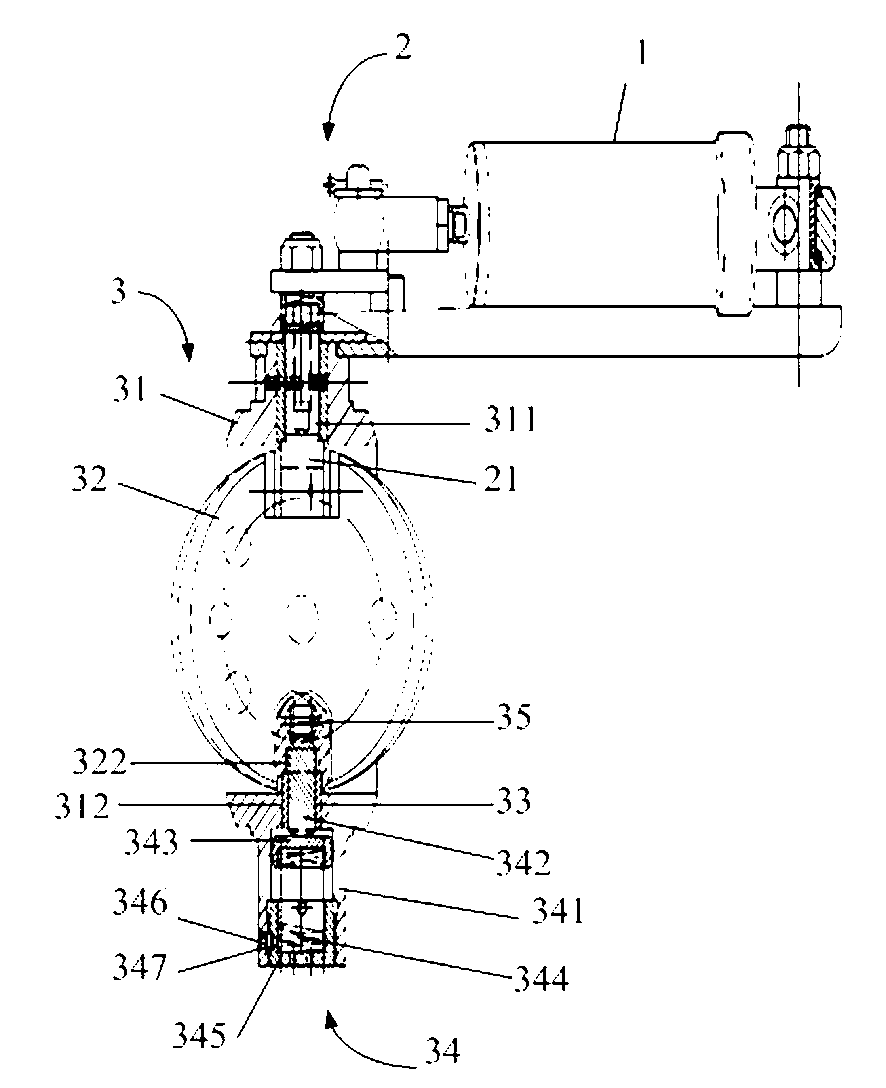
[0032] Please refer to figure 1 The schematic diagram of the auxiliary brake valve of the present invention, the auxiliary brake valve is mainly compos...


PUM


Abstract

The invention provides a pressure limiting and air leaking auxiliary brake valve device with a support guide sleeve. The pressure limiting and air leaking auxiliary brake valve device with the support guide sleeve comprises a valve body, a butterfly sheet, a support device, a pressure regulating device and a pressure leaking port device, wherein a fixed through hole is formed on the valve body; a driving shaft passes through the fixed through hole of the valve body, and the butterfly sheet is fixed in an inner cavity of the valve body, and a fixed notch is formed on the edge of the butterfly sheet; a support hole is also formed on the valve body and is positioned on the valve body of the opposite part of the fixed through hole, and the support hole and the fixed hole are concentric; a support groove is formed on the butterfly sheet and is a round ladder-shaped groove; the support device is a cylindrical guide sleeve which is fixed in the support hole of the valve body; and the guide sleeve protrudes and extends into the inner cavity of the valve body, and is correspondingly inserted in the support groove of the butterfly sheet. The pressure limiting and air leaking auxiliary brake valve device with the support guide sleeve provided by the invention is compact in structure, and effectively controls the motion stroke of a piston tappet, improves the air exhaust back pressure value of an engine at middle and low speeds, guarantees the resistance of the piston tappet in reciprocating motion to be small, prevents an inner spring from being invalid because of high temperature, and enables the service life of the auxiliary brake valve device to be long.

Description

technical field [0001] The invention relates to an auxiliary braking device, in particular to a pressure-limiting and air-releasing auxiliary braking valve device with a supporting guide sleeve for a vehicle. Background technique [0002] The pressure-limiting and air-leakage auxiliary brake valve device is an auxiliary braking device for vehicles, especially suitable for commercial vehicles. Vehicle brake failure to ensure driving safety. [0003] The pressure-limiting and deflated auxiliary brake valve device in the prior art relies on the cylinder or the vacuum booster cylinder to push and pull the drive shaft to deflect to make the butterfly plate deflect. The drive shaft is inserted into the butterfly plate and fixed with rivets, and the force of the drive shaft deflection acts on the rivet , The rivet is easily deformed and broken under a large compressive force, and the butterfly cannot realize its effective movement. [0004] Chinese Patent Nos. 200710137250....

Claims


Application Information

Patent Timeline
Patent Type & Authority Applications(China)
IPC IPC(8): F02D9/06
Inventor 褚志强吴和文王斌钱利春李清清陈磊磊
Owner ZHEJIANG EASUN PNEUMATIC SCI & TECH
Why Eureka
Try Eureka