
High-strength three-dimensional support system of yielding type restriction concrete lagging jack

A technology of concrete arch frame and yielding type, which is applied in the field of deep underground roadway support system, can solve the problems that affect the production and safety of deep rock mass engineering, large deformation of deep soft rock caverns, and unsatisfactory effects, and achieve anti-corrosion The effect of strong deformation capacity, high support strength and high bearing capacity

Inactive Publication Date: 2013-01-02
SHANDONG UNIV
View PDF9 Cites 36 Cited by
  • Summary
  • Abstract
  • Description
  • Claims
  • Application Information

AI Technical Summary

Problems solved by technology

In view of the characteristics of large deformation and difficult support of deep soft rock caverns, special research has been carried out on the support methods of deep high-stress soft rock large-section caverns at home and abroad. However, the effects of these support forms are not very satisfactory. Most of the support resistance is insufficient and the support strength is not high.
In general, under the conditions of deep high-stress soft rock and broken rock mass, roadways and chamber groups exhibit large deformation and difficult support problems. The existing support technology is difficult to fully meet the needs of deep high-stress roadways and chamber groups. The need for support has seriously affected the production and safety of deep rock mass engineering

Method used


Image

  • High-strength three-dimensional support system of yielding type restriction concrete lagging jack
  • High-strength three-dimensional support system of yielding type restriction concrete lagging jack
  • High-strength three-dimensional support system of yielding type restriction concrete lagging jack

Examples


Embodiment Construction

[0022] The present invention will be further described below in conjunction with the accompanying drawings and embodiments.

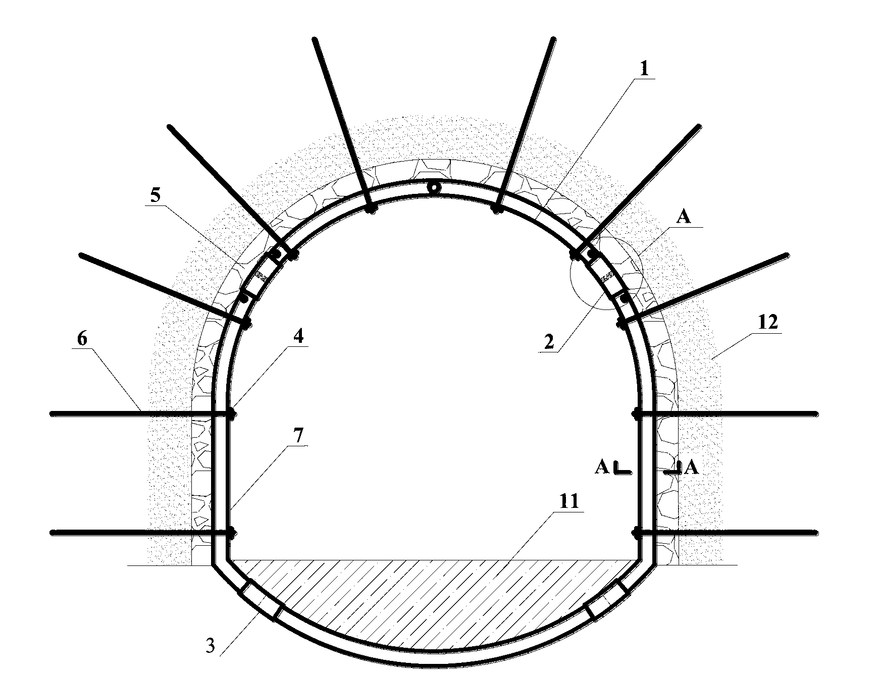
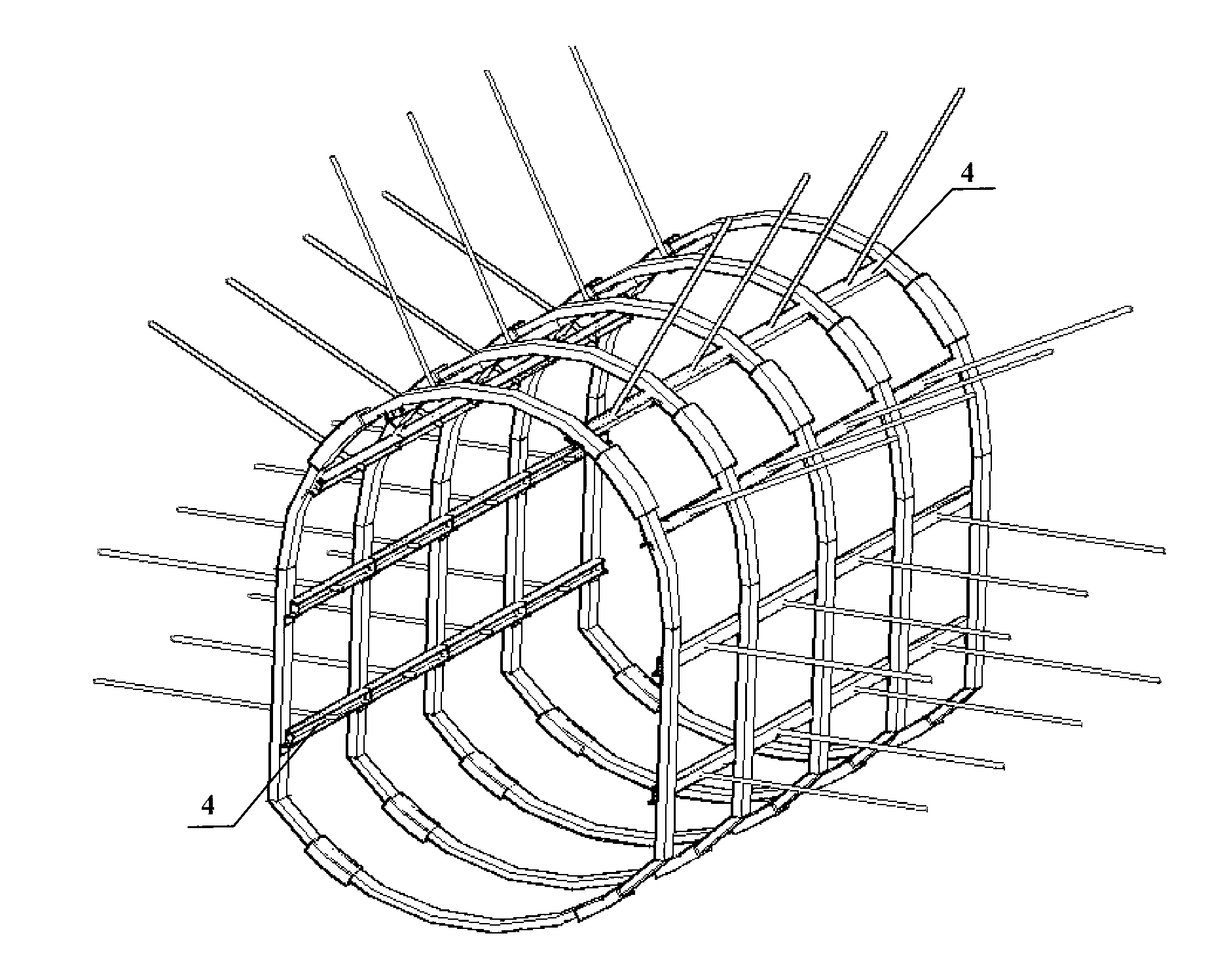
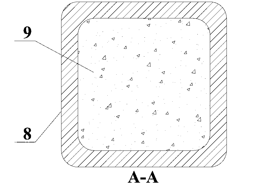
[0023] refer to Figure 1~2 , the specific embodiment of the present invention is that the high-strength three-dimensional support system of the pressure-constrained concrete arch is mainly composed of a constrained concrete arch 1, a pressure node 2, a longitudinal beam 4, and an anchor rod 6. The constrained concrete arch 1 is The closed straight wall arch and inverted bottom arch structure consistent with the shape of the roadway are arranged at a certain distance. 6 passes through the longitudinal beam 4 and then anchors into the surrounding rock 12, and applies prestress to form a squeezing effect on the surrounding rock 12. The anchor rod 6 forms a three-dimensional support system through the longitudinal beam 4 and the constrained concrete arch 1. A leveling and energy-releasing layer 5 is arranged between the constrained concrete arch 1 and the...


PUM


Abstract

The invention discloses a high-strength three-dimensional support system of a yielding type restriction concrete lagging jack, which is mainly formed by a restriction concrete lagging jack, a yielding node, a vertical beam, an anchor rod or an anchor cable, wherein the restriction concrete lagging jack is in a closed structure which is the same as the shape of a roadway and is formed by connecting and combining restriction concrete through a sleeve and the yielding node; the restriction concrete is distributed at an interval and is connected through the vertical beam; the anchor rod or the anchor cable passes through the vertical beam to be anchored into a rock layer; pre-stress is applied so as to form extrusion effect on a surrounding rock; and the lagging jack forms an integral structure with the anchor rod or the anchor cable through the vertical beam, and a space three-dimensional support system is formed by combined action. The high-strength three-dimensional support system is applicable to an underground engineering support including a deep soft rock underground roadway and the like, and has the advantages of high supporting strength, good stability, reasonable stress and the like; and the high-strength three-dimensional support system has a yielding function and can effectively control the stability of a roadway surrounding rock.

Description

technical field [0001] The invention belongs to the field of underground engineering support, in particular to a deep underground tunnel support system. Background technique [0002] With the development of society and economy, more and more underground rock mass projects such as coal mine roadways, highway and railway tunnels and large-scale hydropower stations are being built, and the situation of deep roadways and chamber groups with large buried depth and large cross-sections is gradually increasing. The corresponding support problem is also becoming more and more prominent. In view of the characteristics of large deformation and difficult support of deep soft rock caverns, special research has been carried out on the support methods of deep high-stress soft rock large-section caverns at home and abroad. However, the effects of these support forms are not very satisfactory. Most of the support resistance is insufficient and the support strength is not high. In general,...

Claims


Application Information

Patent Timeline
IPC IPC(8): E21D11/10E21D21/00
Inventor 王琦李术才李智李海燕王德超王洪涛李为腾张红军
Owner SHANDONG UNIV
Learn More