
Oil-water automatic control separation device

A technology for separation equipment and oil-water separation, which is applied in the fields of oil-water automatic control separation equipment, oil-water separation equipment, and petroleum purification equipment. It can solve problems such as waste of resources, pollution of the environment, and large waste of oil resources, and achieve the effect of avoiding waste

Active Publication Date: 2013-01-02
XI'AN UNIVERSITY OF ARCHITECTURE AND TECHNOLOGY
View PDF5 Cites 9 Cited by
  • Summary
  • Abstract
  • Description
  • Claims
  • Application Information

AI Technical Summary

Problems solved by technology

[0011] (1) Incomplete oil-water separation;
[0012] (2) Large waste of oil resources
[0013] (3) A large amount of coal is required for heating in winter
[0014] (4) The oil-water separation accuracy is not high, and the probability of accidents is high
[0015] (5) Most of the natural gas produced in oil extraction is directly discharged, so that no economic effect is achieved and precious resources are wasted
[0016] (6) Pollution of the environment

Method used


Image

  • Oil-water automatic control separation device
  • Oil-water automatic control separation device
  • Oil-water automatic control separation device

Examples


Embodiment Construction

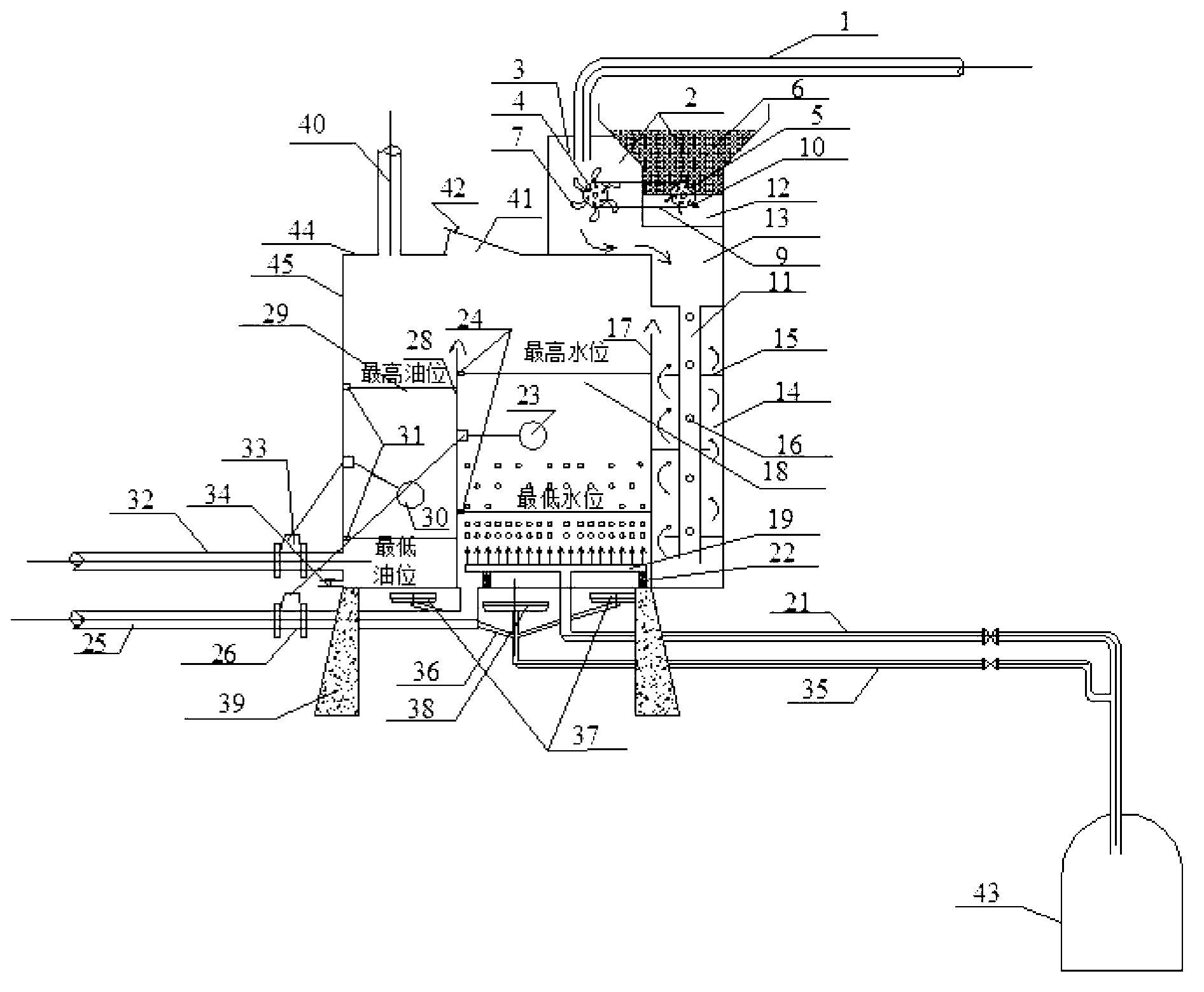
[0048] The main design concept of the oil-water automatic control equipment of the present invention is to organically combine the oil-water separation theory, uniform gas distribution theory, automatic control theory, mixing and energy dissipation theory, etc., and use the natural gas produced in the oil well exploitation process to make it fully utilized , and at the same time combine with the action of drugs to carry out efficient oil-water separation, and finally achieve the purpose of energy saving and emission reduction.

[0049] According to the theory of mutual incompatibility of oil and water under certain conditions, through the characteristics of air flotation and the basic properties of the added medicine, the oil and water can be separated efficiently, and then the separated oil and water will be discharged out of the equipment according to the automatic control system, so as to realize the maintenance of the equipment. cycle. The equipment has simple structure, c...


PUM


Abstract

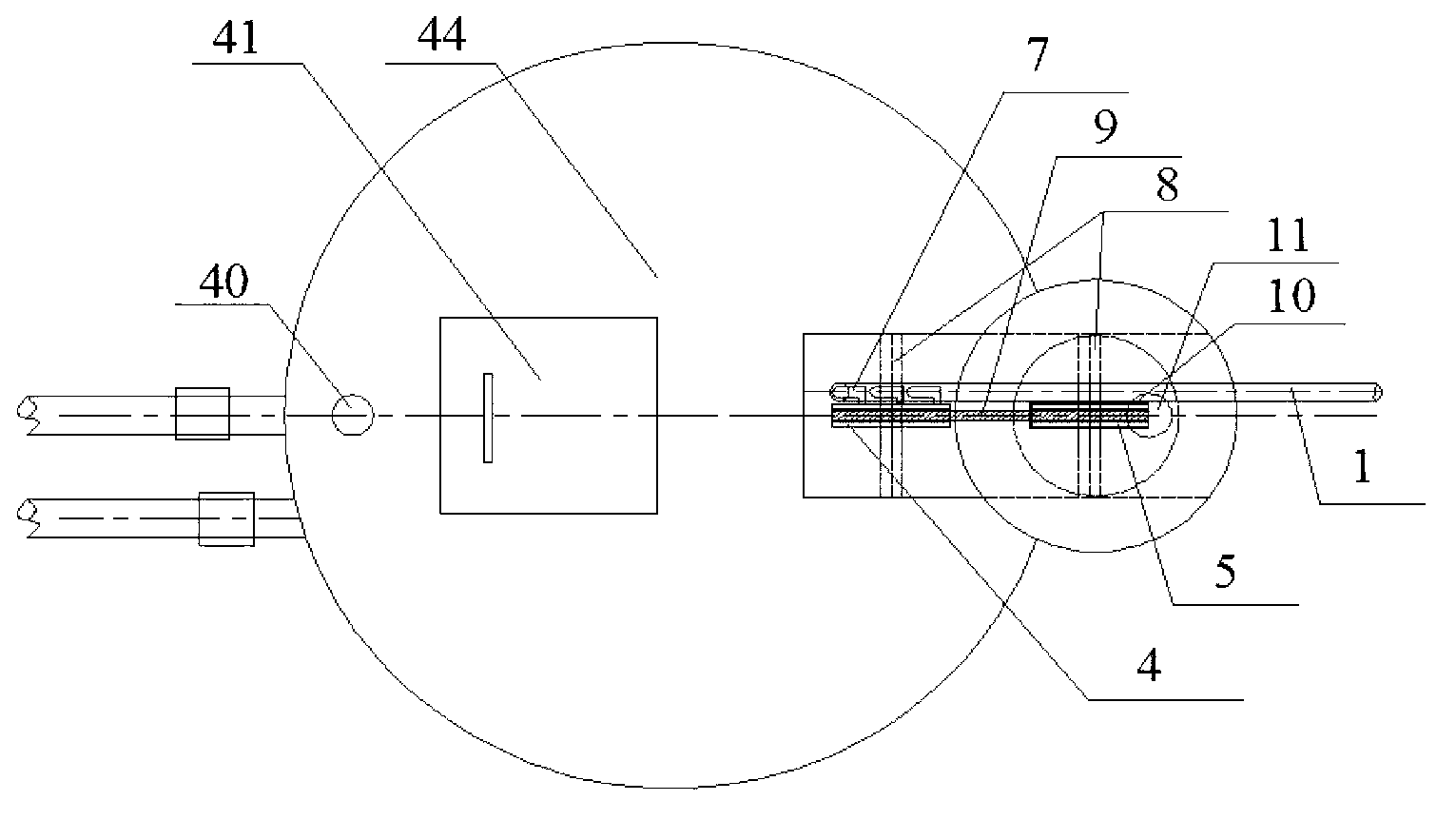
The invention discloses an oil-water automatic control separation device which comprises a cylinder and a device base, wherein an oil-water separation chamber and an oil storage tank are arranged inside the cylinder, and an oil-medicine secondary mixing tank is arranged inside the cylinder; a right protruding circular plate inverted triangular weir is arranged between the oil-medicine secondary mixing tank and the oil-water separation chamber; a left protruding circular plate inverted triangular weir is arranged between the oil storage tank and the oil-water separation chamber; a top cover of the cylinder is a horizontal circular sealing head; the middle of the circular sealing head is an inspection hole; the left side of the inspection hole is an exhaust pipe; and right side of the inspection hole is a medication adding room; semi-closed separation plates are evenly arranged in the oil-medicine secondary mixing tank; gas distribution pipes are evenly paved at the bottom of the oil-water separation chamber; a waste water discharge pipe and a manual control water discharge pipe are arranged at the bottom of the oil-water separation chamber simultaneously; a gas supply pipe of a heater is located in the device base, gas supply is provided by a gas collection tank; and then the gas is provided for a middle heating disc and a high-position heating disc through a heating disc gas supply branch pipe. The oil-water automatic control separation device is simple in structure, complex in distribution, high in space using ratio and simple to operate, and is capable of saving energy and reducing emission.

Description

technical field [0001] The invention relates to oil-water separation equipment in the field of oil exploitation, in particular to an oil-water automatic control separation equipment, which integrates functions such as separation, air flotation, automatic control, dosing, mixing, and energy dissipation, and is a new type of oil-water separation equipment. Purification equipment. Background technique [0002] In recent years, due to the vigorous exploitation of oil in our country, the water content in oil is increasing day by day, while the oil content is getting less and less. The major oilfield companies are faced with greatly increased costs in the oil-water separation process in the later stage of oil pumping. The following is a further analysis from the Shanbei Oilfield in my country as an example: [0003] A. Natural gas: In addition to being an important oil production area in my country, northern Shaanxi is also an important oil and gas production area in my country....

Claims


Application Information

Patent Timeline
IPC IPC(8): B01D17/025B01D17/022B01D17/035
Inventor 卢金锁刘飞胡亚潘
Owner XI'AN UNIVERSITY OF ARCHITECTURE AND TECHNOLOGY
Learn More