
Vibration nipper for heavy machinery

A technology for heavy equipment and vibrating tongs, which is applied in mechanically driven excavators/dredgers, earthmoving machines/shovels, construction, etc., and can solve the problems of obstructing longitudinal vibration, easy damage and tearing of the vibrating tongs 1 , to achieve the effect of improving durability

Inactive Publication Date: 2012-12-26
赵在龙 +1
View PDF8 Cites 6 Cited by
  • Summary
  • Abstract
  • Description
  • Claims
  • Application Information

AI Technical Summary

Problems solved by technology

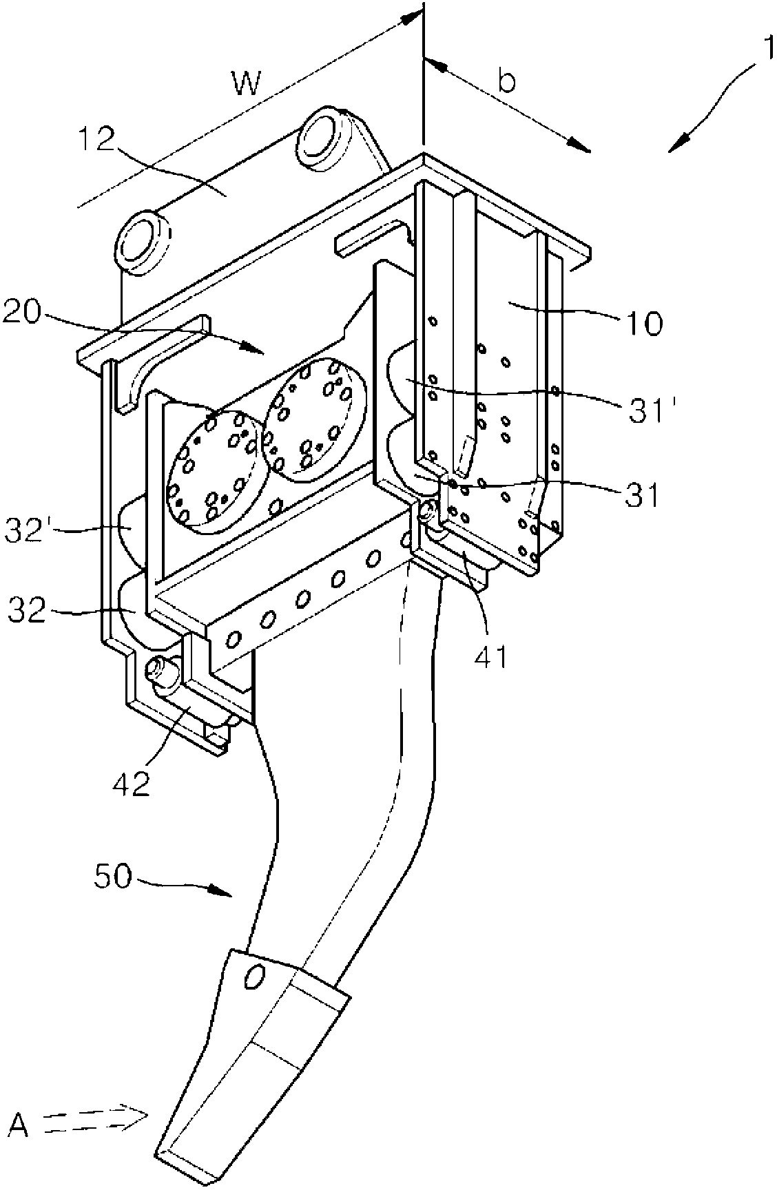
In order to support the excavation resistance, although the vibrating pliers 1 is increased with a plurality of friction support structures 41 and 42, or a plurality of reinforced dust-proof rubbers are installed, it is still difficult to support the excavation resistance, so due to the dust-proof rubbers 31, 31', 32, 32' The deterioration of the cushioning performance or excessive lateral deformation makes the dust-proof rubber 31, 31', 32, 32' easy to tear and hinders the longitudinal vibration
[0010] Therefore, when the digging force is increased, the vibrating tongs 1 are easily damaged, and thus the durability of the vibrating tongs 1 is reduced, and it takes a lot of time to repair or maintain

Method used


Image

  • Vibration nipper for heavy machinery
  • Vibration nipper for heavy machinery
  • Vibration nipper for heavy machinery

Examples


Embodiment Construction

[0031] Hereinafter, exemplary embodiments of the present invention will be described in detail. Wherein, the same reference numerals denote the same elements.

[0032] The vibratory tongs 100 according to an embodiment of the present invention are installed on the arms of heavy equipment such as excavators, bulldozers, and loaders to simultaneously perform crushing and excavation work in civil engineering and demolishing fields.

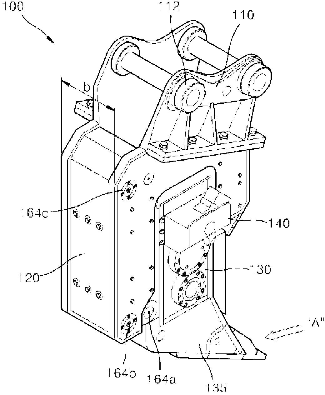
[0033] as in image 3As fully shown in , the vibrating tongs 100 have the structure of: a mounting part 110 formed on the top of the vibrating tongs 100, the mounting part 110 has an arm fixing hole 112 connected to an arm of a heavy equipment, and a frame 120 is approximately in the shape of a ∩ The ground is connected to the bottom of the installation part 110 , the vibrating body 130 is located inside the frame 120 , and the jaws 135 are mounted on the bottom of the vibrating body 130 .

[0034] Such as Figure 4 , Figure 5 and Figure 6 As ...


PUM


Abstract

The present invention relates to a vibration nipper for heavy machinery, wherein a plurality of gears incorporated in a vibration main body and having eccentric weights are aligned in the vertical direction and generate vertical vibration while rotating. Provided is a vibration nipper for heavy machinery, comprising a vibration main body, which gears inside for rotating by a hydraulic motor are aligned in the vertical direction and disposed to be rotatable. The respective gears are mounted with eccentric weights for generating vertical vibration during the rotation of the gears. The vibration main body is mounted with a nipper blade at the lower portion thereof in the longitudinal direction of the vibration main body, so that the vibration main body may be inserted deep into the ground along with the nipper blade at the time of underground excavation. According to the present invention, it is possible to produce the vibration main body in narrower width than existing ones, so that a frame may be produced with reduced width. Therefore, even though the nipper blade is inserted into the ground, the vibration main body may be inserted deep into the ground along with the nipper blade, so that the depth of excavation may be deepen and the performance of excavation may be largely improved. In addition, according to the present invention, even though the nipper blade is applied with excavation resistance in the lateral direction from the ground when the nipper blade excavates the ground, the supporting structure of the nipper blade is improved in the lateral direction by connecting the nipper blade and the vibration main body via a link structure which is displaceable in the vertical direction with respect to the frame. Therefore, the operation of the nipper blade is free and a buffering member for supporting the vibration main body is protected from being damaged, exhibiting much improved durability.

Description

technical field [0001] The present invention relates to a vibrating nipper for heavy equipment capable of effectively breaking and excavating in the field of civil construction and demolition, mounted on heavy equipment such as excavators, bulldozers, and loaders, and more particularly , relates to a vibrating pliers having improved durability, the vibrating pliers including a vibrating body in which a plurality of gears having an eccentric pendulum are longitudinally arranged and rotated and longitudinal vibrations are generated in the following manner, That is, the width of the vibrating body can be made narrow so that the nipper blade (nipper blade) can be deeply inserted into the ground, the frame is connected to the vibrating main body through a connector structure to freely operate the nipper blade, and the built-in Type (built-in) buffer. Background technique [0002] Generally, in the field of construction, to break bedrock, a breaker formed of a plurality of iron p...

Claims


Application Information

Patent Timeline
IPC IPC(8): E02F5/32E02F3/96E02F5/30
CPCE02F5/326
Inventor 赵在龙李正镐
Owner 赵在龙
Learn More