
Method for transferring workpieces to enter and exit vacuum environment and ensuring workpieces to pass through processing region in vacuum environment and equipment

A technology of processing area and workpiece, applied in the field of vacuum transmission process, can solve the problems of low production efficiency and workpiece cannot be processed continuously, and achieve the effect of improving efficiency, saving time and high transmission efficiency

Active Publication Date: 2012-12-26
赛瑞达智能电子装备(无锡)有限公司
View PDF4 Cites 1 Cited by
  • Summary
  • Abstract
  • Description
  • Claims
  • Application Information

AI Technical Summary

Problems solved by technology

[0005] In the existing technology, either the workpiece cannot be processed continuously, or the production efficiency is very low during continuous processing, so how to improve the production efficiency of the vacuum process has become a crucial research topic

Method used


Image

  • Method for transferring workpieces to enter and exit vacuum environment and ensuring workpieces to pass through processing region in vacuum environment and equipment
  • Method for transferring workpieces to enter and exit vacuum environment and ensuring workpieces to pass through processing region in vacuum environment and equipment
  • Method for transferring workpieces to enter and exit vacuum environment and ensuring workpieces to pass through processing region in vacuum environment and equipment

Examples


Embodiment Construction

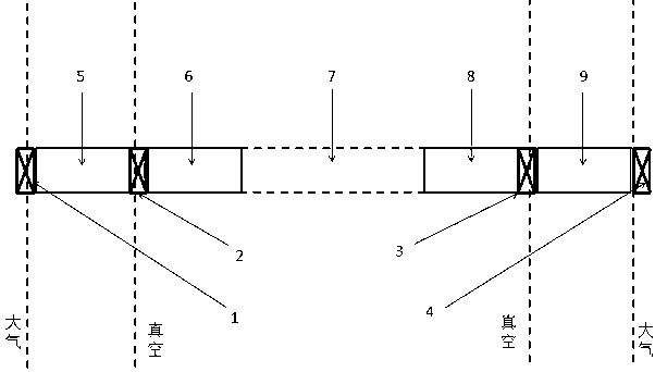
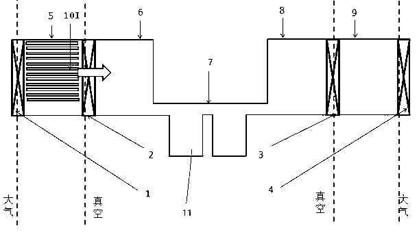
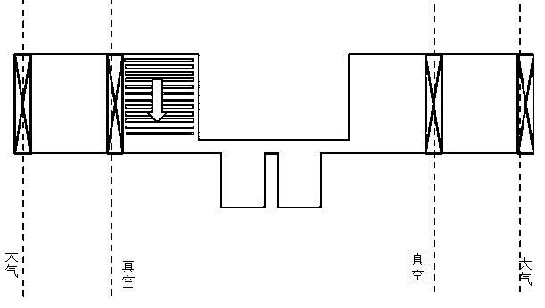
[0051] to combine Figure 1 to Figure 8 , the method and equipment for transferring workpieces in and out of the vacuum and passing through the processing area in the vacuum according to the present invention are described in detail.

[0052] Such as figure 1 As shown, the device for transferring workpieces in and out of the vacuum and passing through the processing area in vacuum according to the present invention, the front buffer zone 6, the processing zone 7 and the rear buffer zone 8 in the middle together form a vacuum process chamber, the front buffer zone 6, the processing zone The 7 and the rear buffer zone 8 communicate with each other.

[0053] The film feeding chamber 5, the vacuum process chamber, and the film discharging chamber 9 are connected through the valve B2 and the valve C3 in sequence. Another valve A1 and a valve D4 are provided in the film feeding chamber 5 and the film discharging chamber 9 respectively. Through the control of valve A1 and valve D4...


PUM


Abstract

The invention provides a method for transferring workpieces to enter and exit a vacuum environment and ensuring the workpieces to pass through a processing region in the vacuum environment. Before the workpieces are processed in the vacuum environment, a front buffer program is executed in a vacuum processing cavity. The program comprises the following steps of: carrying out one-by-one workpiece descending motion on one column of N workpieces; transferring the lowermost workpiece onto a horizontal transmission platform; and transferring the workpieces to the processing region one by one by the horizontal transmission platform to carry out processing. The invention also provides equipment for implementing the method, which comprises the vacuum processing cavity. The vacuum processing cavity is divided into a front buffer region, the processing region and a rear buffer region which are sequentially arranged; the horizontal transmission platform runs through the front buffer region, the processing region and the rear buffer region in the vacuum processing cavity; and lifting devices are arranged in the front buffer region and the rear buffer region. The method and the equipment have the advantages that in the workpiece transmission process, the workpieces always take the linear motion without turning; the transmission efficiency is high; the motion mode is simple; the design is also simple; a small number of mechanical parts are required; the cost is low; and the reliability is high.

Description

technical field [0001] The invention relates to the field of vacuum process, in particular to a method and equipment for vacuum transmission process. [0002] Background technique [0003] In some solar cell manufacturing industries, the processing of many workpieces needs to be carried out in a vacuum environment. Inevitably, it is necessary to send the workpiece from the normal temperature and pressure environment into the vacuum and take it out from the vacuum to the normal temperature and pressure. The whole reaction process needs to be vacuumed and broken many times, which is not only cumbersome but also consumes energy and wears out equipment. [0004] Moreover, when different batches of workpieces enter and leave the vacuum environment, or when switching from processed workpieces to the next batch of workpieces to be processed in the vacuum environment, the machining process of the workpieces by the processing device has to be interrupted. During the period of time,...

Claims


Application Information

Patent Timeline
IPC IPC(8): H01L21/677H01L31/18
CPCY02P70/50
Inventor 张海林姚飞宋银海
Owner 赛瑞达智能电子装备(无锡)有限公司
Learn More